Now I have a simulation and strangely it seems to oscilate:
1st pic Vout
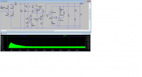
2nd pic Current on the 2N5457
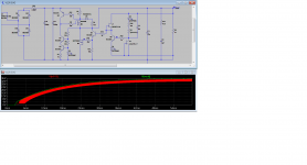
3rd pic BC546 Vb
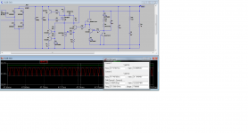
4rth pic BC546 Vb detail
5th pic IRFP9240 Vgate
1st pic Vout
2nd pic Current on the 2N5457
3rd pic BC546 Vb
4rth pic BC546 Vb detail
5th pic IRFP9240 Vgate
Attachments
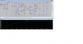
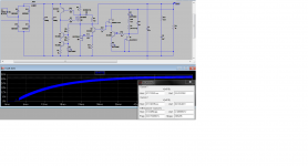
Initially, for a short time the shunt regulator output sits at around 3V while the 4.7uF feedback cap charges, but then the shunt reg voltage ramps up to the desired output voltage.
My sim confirms that behaviour
P.S. If it was a finalized thing for general builds on a proper PCB it would need some sure start mechanism to avoid any chance of stalling of course.
I am planning a layout for a pcb....
")
Bypassing the compound transistor BC550C over the IRFP9240 totally eliminates the issue.
Remove R11 in that case also
In my old prototype I had no nasties with the final particular layout, else the phono FFT would be full of harmonic noises. Its a sensitive circuit because CFP. I will have to practically revisit it for you if you can wait, try the RC compensator around the error amp transistor as seen in 1.2 for now? Then scope again. Although 94MHZ is very high, can it be picking noise easily over the sense lines when the CFP makes it faster than when bypassed, and not an oscillation? I would expect any instabilities in the 2-6MHZ. PSUs are measured over a 20MHz bandwidth limit in the industry. Shield the sense lines?
What happens to the RF you see when you turn the power off to the device under test?All my V12R builds sound astounding so maybe you are right and my measuring setup is picking external influences.
What happens to the RF you see when you turn the power off to the device under test?
Slowly disappears from the scope screen,,,,,
So the nasties are not from the shunt but being picked up from the environment.
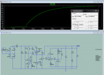
Anyway, I just tamed the simulator.
It all depends on the termination zobel.
Too much resistance and the thick line appears.
Too low capacitance... the same...
Too high capacitance and the results are even worse.
What I need now is a good way to determine the exact values for the zobel, minimizing the cap value.
Below 15uF, with any resistance in the zobel, the thick line appears.
fixing to 15u I found that I can use 0.05ohms to get a perfect picture.
How can I determine the best zobel values ?
Attachments
Anyway, what do you think about the simulation particularities ?
I can't replicate the thick driving line in my original simulation
Slowly disappears from the scope screen,,,,,
So the nasties are not from the shunt but being picked up from the environment.
Anyway, I just tamed the simulator.
It all depends on the termination zobel.
Too much resistance and the thick line appears.
Too low capacitance... the same...
Too high capacitance and the results are even worse.
What I need now is a good way to determine the exact values for the zobel, minimizing the cap value.
Below 15uF, with any resistance in the zobel, the thick line appears.
fixing to 15u I found that I can use 0.05ohms to get a perfect picture.
How can I determine the best zobel values ?
Use the 20MHZ bandwidth limit in the scope. My original sim has ESR and ESL in the caps
post6872
you quoted his text and replied to the question !!!!device under test
- Status
- This old topic is closed. If you want to reopen this topic, contact a moderator using the "Report Post" button.
- Home
- Amplifiers
- Power Supplies
- The simplistic Salas low voltage shunt regulator