Which schematic have you used?
link or post.
Dear Mr. Andrew,
Schematic for tone control is not available , only the layout. its from Apex audio. I have modified it to include the volume pot. its available in post # 505.
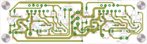
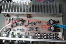
the amplifier pcb is again by apexaudio and the link is http://www.diyaudio.com/forums/chip-amps/162099-lm3886-schematics-pcb.html. The PCB layout is as per the attached image designed by Bimo.
reg
Prasi
Attachments
Dear Mr. Andrew,
Schematic for tone control is not available , only the layout. its from Apex audio. I have modified it to include the volume pot. its available in post # 505.
the amplifier pcb is again by apexaudio and the link is http://www.diyaudio.com/forums/chip-amps/162099-lm3886-schematics-pcb.html. The PCB layout is as per the attached image designed by Bimo.
reg
Prasi
in this stage no one can help you but here is possible error
1.fault in circuit design of that amplifier pcb but it is rare thing.
2.poor speaker.
3.low power transformer
4.bad cap and unbalance dc.
5.something wrong did by you.
everyone can only suggest you in the end you have to do it yourself.
some time if we use preamp then it give high signal to amp and amp reach it peak power then distortion is normal.
Last edited:
1. The amp has been tested by bimo also.in this stage no one can help you but here is possible error
1.fault in circuit design of that amplifier pcb but it is rare thing.
2.poor speaker.
3.low power transformer
4.bad cap and unbalance dc.
5.something wrong did by you.
everyone can only suggest you in the end you have to do it yourself.
some time if we use preamp then it give high signal to amp and amp reach it peak power then distortion is normal.
2. Speakers used are Diy floor standing with f3 of 40hz. I am using same speakers to compare commercial amp and Diy apex gainclone amp. Comercial amp sound is more open and deeper bass and sound is not harsh on ears.
3. Toroid 300va transformer used.
4. All caps are imported ones by epcos and chemicon in the amp. Tone control caps are local.
5. Hopefully I have done everything correctly. Volume bass and treble pots are working as intended.
Anyway let's see. I am also building kelvin amp. Hopefully its sound is better.
Reg
Prasi
Which schematic have you used?
link or post.
I am waiting for some calculations from Mr. Andrew. I know he is a genius in calculations and hopefully he can suggest some cap and resistor values that can improve the sound of this gainclone and tone control.
Which schematic have you used?
l.............
.................
Schematic for tone control is not available .................
I am not a clairvoyant.I am waiting for some calculations from Mr. Andrew...............
I am not a clairvoyant.
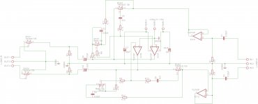
mr. andrew,
attaching herewith the schematic. its not pretty but rest assured, the pcb layout as per post 505 and the attached schematic are consistant.
regards
prasi
Attachments
Subwoofer X-over with inputs from line or speakers.
Hi APEX,
can we convert your subwoofer x-over to line level and speaker level to mono signal converter ?(without any crossover functions)
It would be useful for anyone looking to convert stereo signals to mono OR speaker level stereo to mono. Can this be implemented in your sub-x-over PCB?
e.g. removing the pots and shorting the input and output pins together on volume control pot. will this achieve the above purpose?
regards
prasi
Where i can find pcb for this pream?Replace 33k resistors with 20k
Is this bjt bc series suitable for this?
Where i can find pcb for this pream?
Is this bjt bc series suitable for this?
What is post number with this preamp circuit?
Hi Mile,
I hope you are still following this thread. I am building the guitar amp and have a few questions. Can I use 0R22 or 0R33 for the emitter resistors? 0R27 are difficult to source.
It appears the psu is built in. What voltage range is suitable for the transformer?
What VA rating is needed?
How much heatsink is needed?
Thanks, Terry
Hi Mile,
I hope you are still following this thread. I am building the guitar amp and have a few questions. Can I use 0R22 or 0R33 for the emitter resistors? 0R27 are difficult to source.
It appears the psu is built in. What voltage range is suitable for the transformer?
What VA rating is needed?
How much heatsink is needed?
Thanks, Terry
You can use 0R22 or 0R33, use 100VA transformer 2x24vac... heatsink size for AB class amplifier.
Regards
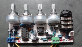
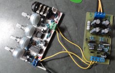
The parts came in so I finished one of the little Tone Preamp channels. Works pretty well. I haven't tried a mic yet but I did plug a guitar into it. Nice range on the tone controls. I powered it with a little ESP P05. Puts out +-15vdc with a 12.6-0-12.6vac transformer.
Blessings, Terry
Blessings, Terry
Attachments
You can use 0R22 or 0R33, use 100VA transformer 2x24vac... heatsink size for AB class amplifier.
Regards
Hi Mile,
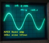
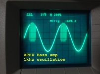
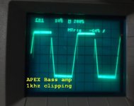
I have the bass amp playing. There are a couple of issues that you may be able to help with. One is that just before it clips I see oscillation on the top of the sine wave. That happens at about 15Vac on the output into an 8ohm load. You can see the attached photo. Another thing is that I am getting 1.8mV across the 0R22 emitter resistors. That is only about 8mA bias. I haven't tried geting the amp to warm up at all but at 8mA it probably won't develop much heat. I haven't played any music through it, only sine waves. The muting circuit works fine with a J111 installed for the jfet. I'm using a 100VA 22-0-22vac transformer. I get +-32vdc unloaded and it drops to about +-28vdc under load. Any suggestions are welcome.
Blessings, Terry
Attachments
Hi Mile,
I have the bass amp playing. There are a couple of issues that you may be able to help with. One is that just before it clips I see oscillation on the top of the sine wave. That happens at about 15Vac on the output into an 8ohm load. You can see the attached photo. Another thing is that I am getting 1.8mV across the 0R22 emitter resistors. That is only about 8mA bias. I haven't tried geting the amp to warm up at all but at 8mA it probably won't develop much heat. I haven't played any music through it, only sine waves. The muting circuit works fine with a J111 installed for the jfet. I'm using a 100VA 22-0-22vac transformer. I get +-32vdc unloaded and it drops to about +-28vdc under load. Any suggestions are welcome.
Blessings, Terry
Nice work, measure voltage on 16V zeners, replace 4x2k7 with 2k2 to get 16V on zeners... increase value of 10pF and 15pF caps for compensations.
- Home
- Live Sound
- PA Systems
- Mic, Line, EQ... Preamps