My preference would be to always keep fir1 at correct gain. X8 or X1 for NOS.. Maybe more a hunch than anything but I think changing gain at FIR1 will alter the sound of the filter in uncontrolled ways.
All filters are linear, especially it should not matter where you apply the gain, or even if you apply the gain in several steps at different locations ... as long this results not in some clipping or resolution problem.
At least that's the theory. If it would really matter where to apply the gain that would be something strange that should be further investigated.
Just reading the patent and there is a long discussion about apparent loss of high frequency information due to time smear.
http://patentimages.storage.googleapis.com/pdfs/US6337645.pdf
Hi, Paul this is very very interesting.
So the filters are all linear, have about the same THD, yet they can sound very different, some sound very transparent, lots of micro detail and others veiled.
Makes me think of my first steps in DIY: I had a NAD amplifier that had good specs but didn't sound transparent, no soundstage.
I made a KT88 PP IT tube amplifier without global NFB and that sounded very transparent, yet the distortion numbers are probably much worse.
Although here with the filters we're working in the digital domain but maybe this kind of distortion, time smearing has also an equivalent in the analog domain.
Just speculating
") but that's for another thread.
but that's for another thread.Paul, thanks for the great work !!!
Last edited:
You can also find a relation between the width of the transition band and the impulse response.Anyway at least we might now make some progress rather than stuffing around trying to tweak impulse responses to look nice.
Perhaps not is the linear impulse response what we have to look for, and yes impulse response in dB.
The temporal duration and upward and downward slopes in the Log Squared Impulse Response.
I bet by the filters with the shortest time response energy.
I bet by the filters with the shortest time response energy.
This is from the Pflaumer patent...
Since this is equivalent to the convolution of the impulse response of the new filter with the impulse response of the previous combination, the total length of the impulse response is greater. This does not have to mean that it will sound worse. The part of the response curve Which is most significant sonically is the region above about minus 80 dB. It is possible to pick a filter design which has less time dispersion at higher amplitudes and more dispersion at very low amplitudes, which sounds as if it has better high frequency resolution than the system without the added alias correction filter.
Last edited:
All filters are linear, especially it should not matter where you apply the gain, or even if you apply the gain in several steps at different locations ... as long this results not in some clipping or resolution problem.
At least that's the theory. If it would really matter where to apply the gain that would be something strange that should be further investigated.
What I was thinking was that because the effect of the filter varies depending on the amplitude of the signal (see log squared impulse response) that applying attenuation in FIR1 will have an effect on the way a signal is processed by later filters in the chain.
Filter Tuning
The main thing I'm taking from Pflaumer is the discussion of the impulse response, not details of his filters.
Basically the point is that the linear impulse response doesn't tell us anything that relates to listening impressions.
As example, I've overlaid two impulse response - purple shows the "hf rolled off Nyquist filter" blue the CRaPMagic (which a few people seem to like).
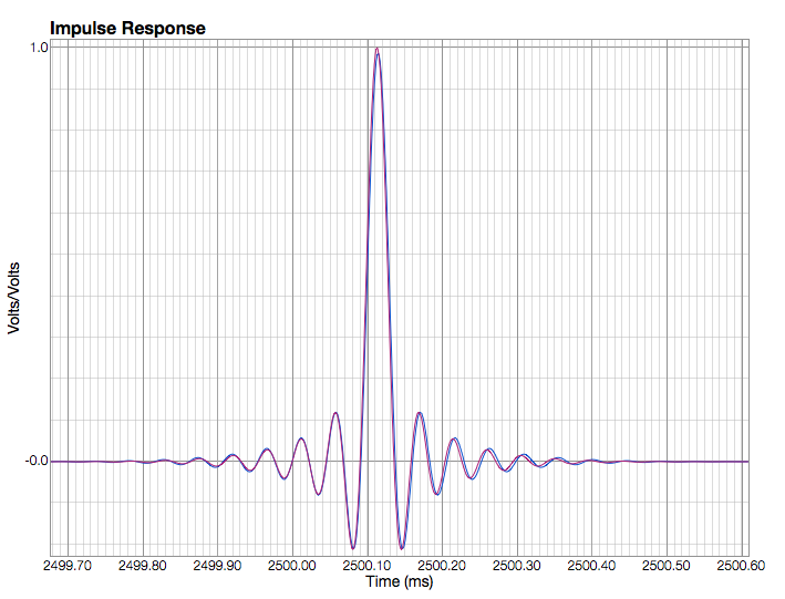
What does that tell you? The purple trace is slightly shorter and has marginally less ringing, so should we assume this sounds "better"? In some regards it does but it's pretty compromised in tonal balance to my ears.
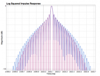
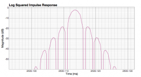
So what happens if we look at the two as a Log squared Impulse Response...

We can immediately see that the CRapMagic has slightly more "time smear" at lower amplitudes. It's not much - I'd guess something like 0.1ms difference at -100dB - but it is enough to alter the tonal balance and the perception of the amount of "detail" in the recording.
tbc
The main thing I'm taking from Pflaumer is the discussion of the impulse response, not details of his filters.
Basically the point is that the linear impulse response doesn't tell us anything that relates to listening impressions.
As example, I've overlaid two impulse response - purple shows the "hf rolled off Nyquist filter" blue the CRaPMagic (which a few people seem to like).
What does that tell you? The purple trace is slightly shorter and has marginally less ringing, so should we assume this sounds "better"? In some regards it does but it's pretty compromised in tonal balance to my ears.
So what happens if we look at the two as a Log squared Impulse Response...
We can immediately see that the CRapMagic has slightly more "time smear" at lower amplitudes. It's not much - I'd guess something like 0.1ms difference at -100dB - but it is enough to alter the tonal balance and the perception of the amount of "detail" in the recording.
tbc
Attachments
Thanks for all your efforts Spzzzzkt, I'm learning a heap
No problem, I'm pretty much documenting what I'm learning as I go along.
OK, so yet another filter.
I think the Nyquist 44.1 filter is probably getting close to as right it will ever be. It's really a matter of tuning the balance now. I've attached a version that is very similar to the CRaPMagic in terms of LSIR. This has the transition band width increased by 1kHz over the NQtb65.
If anyone wants to post feedback on these filters in terms overall frequency response, detail vs foreground balance etc I should be able to try to juggle things to get a result.
Attachments
No problem, I'm pretty much documenting what I'm learning as I go along.
OK, so yet another filter.
I think the Nyquist 44.1 filter is probably getting close to as right it will ever be. It's really a matter of tuning the balance now. I've attached a version that is very similar to the CRaPMagic in terms of LSIR. This has the transition band width increased by 1kHz over the NQtb65.
If anyone wants to post feedback on these filters in terms overall frequency response, detail vs foreground balance etc I should be able to try to juggle things to get a result.
I still think it's too smooth, it sounds very organic and nice but 35 has more dynamics still, but I have older ears.
I still think it's too smooth, it sounds very organic and nice but 35 has more dynamics still, but I have older ears.
Did you listen to the NQtb65 version? I think that is closer to where the filter will end up. NQtb75 is a little too polite.
oops sorry I was comparing the 35 to NQv4RG, will try the 65 and 75 later today.
I like the 35 because it has more of a 3D sound, better depth , more layering, things I suspect have their attributes from phase performance, although I know SFA about filters compared to your stellar investigations.
I like the 35 because it has more of a 3D sound, better depth , more layering, things I suspect have their attributes from phase performance, although I know SFA about filters compared to your stellar investigations.
I think the Nyquist 44.1 filter is probably getting close to as right it will ever be. It's really a matter of tuning the balance now. I've attached a version that is very similar to the CRaPMagic in terms of LSIR. This has the transition band width increased by 1kHz over the NQtb65.
If anyone wants to post feedback on these filters in terms overall frequency response, detail vs foreground balance etc I should be able to try to juggle things to get a result.
First impression: I feel that the NQtb65 is an inprovement over theIPv4_pxx.skr, "less curtain" and noticeable better spatial resolution. The NQtb75 also has perhaps some "less curtain" effect, but not that spatial resolution.
I still think 35 is more to my taste and system compared to 65. It's tighter, images slightly better , but it's so close I'd be happy with either. Can you do a " minimum phase" version of this ? Probably a dumb question.
Unfortunately there doesn't seem to be a way to do minimum phase with the nyquist filters. Don't worry it's not an either/or proposition. I'll come back to the p35, but just want to focus on these filters for the moment.
What I was thinking was that because the effect of the filter varies depending on the amplitude of the signal (see log squared impulse response) that applying attenuation in FIR1 will have an effect on the way a signal is processed by later filters in the chain.
I am not sure if I understand your argument correctly. The effect of the filter to an signal of half of the amplitude is to put out half of the full output. I see no real illumination by the impulse plot. For an impulse of half amplitude you get the same graph shifted down by 6dB. But I think that has nothing to do with the "width of the impulse response"-argument, which applies to the FS graph.
What is an positive effect of scaling the filter coefficients as big as possible (i.e. not resulting in exceeding the headroom or resulting in intermediate clipping) is that you conserve more information of the initial double coefficients when converted in 2.30-fixed floats by mkrom. Thus the convolution will be more exact. But you need to adjust the gain at some point and will loose the last bits there ... I have not yet thought about if some benefit remains.
But I think we have plenty enough of precision. You say e.g. that the width of the impulse response at 100 dB is of importance. The impulse response ist just the plot of the filter coefficients. So we are interested on the length of the interval that contains coefficients larger than 10^{-5}, that is approximately that the first 16 MSB bits are not zero. We are computing for the magnitude with 31 bits.
Nevertheless,
@Soren, a petition:
It should not cost to much FPGA resources to implement the coefficients as "partial floats", and avoid any headache about their precision.
You could store the coefficients as mantissa and shift in LSB direction. That would only add a shift of the bits after every multiplication of the convolution in the accumulator.
Last edited:
I am not sure if I understand your argument correctly. The effect of the filter to an signal of half of the amplitude is to put out half of the full output. I see no real illumination by the impulse plot.
No, you don't.
It probably doesn't make too much difference with FIR2, but basically you are shifting the signal downwards vs the response of the filter. The further you attenuate the input to the filter the greater the time smear from the impulse.
Probably not much of an issue in the greater scheme of things.
Attachments
Last edited:
I think you are rigth that may be an important factor.This is from the Pflaumer patent...
I was doing Fuzzmeasure measures from 0 to -50 dB of LSIR, and filters I liked were those that accumulate energy in less milliseconds above those -50 dB.
I put these measures in the last two PDF.
All shorter filters comply this, like NOS filter.
But there can be long filters if are designed to concentrate power than -50 db in less milliseconds.The filter 1021filtNqF2.skr measure very well, and sounds great. It was a very good impulse response in dB, superior to the rest of filters impulse except NOS and sound very nice, no strident, no disturb.
And if they are short sloping upward than downward, above -50 dB, is better, like IP or apodizing filters.
No, you don't.
It probably doesn't make too much difference with FIR2, but basically you are shifting the signal downwards vs the response of the filter. The further you attenuate the input to the filter the greater the time smear from the impulse.
Probably not much of an issue in the greater scheme of things.
I understand what you mean, but I do not believe that's the right way of looking at it. The filter must be shifted that it has unity gain to make comparable results. The "time smear" will reappear or vanish again if you shift (add or remove gain) later.
But as you said this discussion is probably pointless at the minor gain shifts applied here.
P.S. As I mentioned elsewhere, you get exactely the the same thing by (upsampe_x8, FIR1, upsample_x8) or (upsample_x64, uFIR1), where uFIR1 is the upsampled version of FIR1.
As convolution is commutative, uFIR1 * FIR2 is the same as FIR2 * uFIR1. Loosely speaking the order of applying FIR1 and FIR2 does not matter (in the right setting).
Last edited:
Nevertheless,
@Soren, a petition:
It should not cost to much FPGA resources to implement the coefficients as "partial floats", and avoid any headache about their precision.
You could store the coefficients as mantissa and shift in LSB direction. That would only add a shift of the bits after every multiplication of the convolution in the accumulator.
Hear hear!!!
//
- Home
- Source & Line
- Digital Line Level
- Filter brewing for the Soekris R2R