I measured the Hafler XL 280 and various modifications of the MyRef. I remember the original MyRef designer also posted his data quite early in the thread. Here,
http://www.diyaudio.com/forums/chip-amps/54571-my-audiophile-lm3886-approach-9.html#post683346
I need to run now. Will see if I can find my measurements later.
http://www.diyaudio.com/forums/chip-amps/54571-my-audiophile-lm3886-approach-9.html#post683346
I need to run now. Will see if I can find my measurements later.
This is a fairly standard way of measuring Zo by shorting the input and feeding a 1A constant current into the amp output.I measured the Hafler XL 280 and various modifications of the MyRef. I remember the original MyRef designer also posted his data quite early in the thread. Here,
http://www.diyaudio.com/forums/chip-amps/54571-my-audiophile-lm3886-approach-9.html#post683346
Mauro shows an improvement from 0R6 in the first example to better than R01 @ 20kHz in the 3rd version.
It's very likely Tom's AP uses an identical method.
But Mauro shows sims NOT measurements. Are your numbers sims too ... or actual measurements like Tom's?
It's very easy to feed a large frequency independent constant current in a sim. MUCH more difficult in real life.
And I'm not sure why you regard <0R1 Zo an advantage if you are using current drive in your speakers.
This is where I started to understand the measurement. If anyone is interested there are a series of discussions throughout. Sorry, it would take me as much time as anyone else to go through it. I really do not want to spend the time to dig out individual links since the journey was an important experience for me, it might be worth for whomever else is interested to go through it. AndrewT seemed to have followed through the thread during that time.
http://www.diyaudio.com/forums/chip-amps/54571-my-audiophile-lm3886-approach-332.html#post2819906
The damping measurements before this had the inputs open.
http://www.diyaudio.com/forums/chip-amps/54571-my-audiophile-lm3886-approach-332.html#post2819906
The damping measurements before this had the inputs open.
Last edited:
The damping measurements before this had the inputs open.
I'm confused now. What are you talking about? The damping factor is measured on the amplifier output. I'm still not clear on which definition of DF you use. I'm only aware of one definition: DF = Zload/Zout. You discarded that earlier but have not provided a substitute.
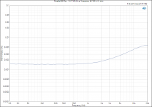
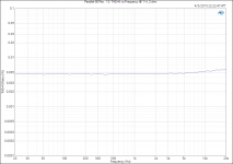
I measure Zout as function of frequency by pulling an AC current out of the amplifier with the amplifier output driven to 0 V. The output impedance as function of frequency can then be derived (by the test equipment) as Zout = Vout/Iout.
Attached is the Zout vs Frequency measurement for the Modulus-86 Rev. 1.0. I expect Zout for Modulus-86 Rev. 2.0 and Parallel-86 to be considerably lower than this. At least 100 mΩ lower as shown in the second plot (which is actually measured on the Modulus-86 Rev. 2.0 prototype).
~Tom
Attachments
Parallel-86 Measurements Part I: 8 Ω
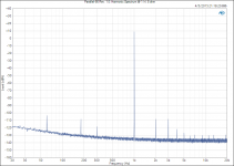
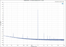
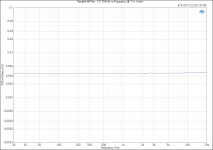
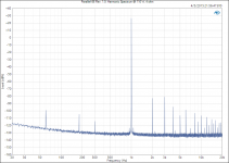
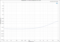
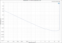
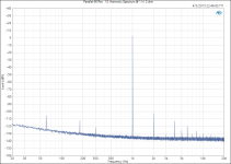
Busy night in the lab. Attached data shows the performance of the Parallel-86 with an 8 Ω load.
The amplifier provides 60 W at the onset of clipping. I've measured at 55 W to show the performance just before clipping.
The supply voltage was ±35 V.
~Tom
Busy night in the lab. Attached data shows the performance of the Parallel-86 with an 8 Ω load.
The amplifier provides 60 W at the onset of clipping. I've measured at 55 W to show the performance just before clipping.
The supply voltage was ±35 V.
~Tom
Attachments
-
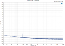 Parallel-86 Rev. 1.0_ Noise Floor.png29.7 KB · Views: 132
 -
 Parallel-86 Rev. 1.0_ Harmonic Spectrum @ 1 W, 8 ohm.png31.8 KB · Views: 132
 -
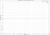 Parallel-86 Rev. 1.0_ THD+N vs Frequency @ 1 W, 8 ohm.png18.6 KB · Views: 142
 -
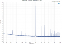
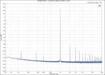 Parallel-86 Rev. 1.0_ Harmonic Spectrum @ 55 W, 8 ohm.png32.8 KB · Views: 436
 -
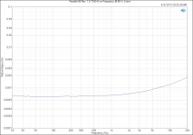 Parallel-86 Rev. 1.0_ THD+N vs Frequency @ 55 W, 8 ohm.png19.4 KB · Views: 439
 -
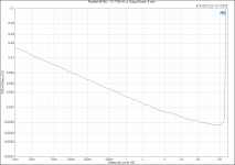 Parallel-86 Rev. 1.0_ THD+N vs Output Power, 8 ohm.png25 KB · Views: 448
Last edited:
Parallel-86 Measurements Part II: 4 Ω
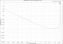
120 W into 4 Ω at the onset of clipping. I measured at 110 W to allow some margin.
The supply voltage was ±35 V.
~Tom
120 W into 4 Ω at the onset of clipping. I measured at 110 W to allow some margin.
The supply voltage was ±35 V.
~Tom
Attachments
-
 Parallel-86 Rev. 1.0_ Harmonic Spectrum @ 1 W, 4 ohm.png31.3 KB · Views: 108
 -
 Parallel-86 Rev. 1.0_ THD+N vs Frequency @ 1 W, 4 ohm.png18.5 KB · Views: 112
 -
 Parallel-86 Rev. 1.0_ Harmonic Spectrum @ 110 W, 4 ohm.png33.1 KB · Views: 117
 -
 Parallel-86 Rev. 1.0_ THD+N vs Frequency @ 110 W, 4 ohm.png20 KB · Views: 109
 -
 Parallel-86 Rev. 1.0_ THD+N vs Output Power, 4 ohm.png25.1 KB · Views: 121
Parallel-86 Measurements Part III: 2 Ω
....and the measurements for 2 Ω load.
The supply voltage was reduced to ±28 V to keep the peak output current below the 7 A per channel specified for the LM4780.
The max output power into 2 Ω is a hair above 120 W. I measured at 100 W to have a little margin.
It's interesting to note that the THD bottoms out around 70 W and rises a bit before the amplifier hits the supply rails.
Overall, this is a solid amplifier. I feel completely confident recommending that the Parallel-86 is operated on ±35 V rails with 4 Ω speakers, even if these speakers have impedance dips below 4 Ω. This amplifier is also an ideal candidate for a bridged amplifier configuration.
To purchase PCBs, please visit my website: Neurochrome :: Audio :: Parallel-86
~Tom
Attachments
-
 Parallel-86 Rev. 1.0_ THD+N vs Output Power, 2 ohm.png24.6 KB · Views: 110
 -
 Parallel-86 Rev. 1.0_ THD+N vs Frequency @ 100 W, 2 ohm.png19.7 KB · Views: 93
 -
 Parallel-86 Rev. 1.0_ Harmonic Spectrum @ 100 W, 2 ohm.png32.7 KB · Views: 105
 -
 Parallel-86 Rev. 1.0_ THD+N vs Frequency @ 1 W, 2 ohm.png19.2 KB · Views: 101
 -
 Parallel-86 Rev. 1.0_ Harmonic Spectrum @ 1 W, 2 ohm.png31.7 KB · Views: 95
Last edited:
I'm interested in whether your numbers/data/pics are sims or measurements.This is where I started to understand the measurement. If anyone is interested there are a series of discussions throughout. Sorry, it would take me as much time as anyone else to go through it. I really do not want to spend the time to dig out individual links since the journey was an important experience for me, it might be worth for whomever else is interested to go through it.
Tom has now posted measurements done in EXACTLY the same way as the 'measurements' on Mauro's thread. eg as described by UnixMan and others.
And you haven't told us why you are interested in sub 0R1 Zo for a current drive amp.
_______________________
Tom, are those THD20k figures at well below 10ppm??
 I grovel at your feet in awe.
What's the bandwidth on the AP?
_______________________
PS Talking about Zo instead of DF might be easier for Soong to understand ... but then again, it might not
Last edited:
I think I am reading the data correctly when I see 10ppm @ 6kHz for 8r0 and @ 2kHz for 4r0.................Tom, are those THD20k figures at well below 10ppm??
All the 2r0 tests and all the 1W tests are above 10ppm at all frequencies.
I stand corrected.I think I am reading the data correctly when I see 10ppm @ 6kHz for 8r0 and @ 2kHz for 4r0.
All the 2r0 tests and all the 1W tests are above 10ppm at all frequencies.
These are still excellent figures. May I get up now
Loudspeakers draw nonlinear currents. Especially the woofers. There is a lot of THD in the current actually. Measure it, you'll see. So, if the drive impedance is high enough (including cables), harmonic currents from the woofer will create a voltage at the speaker terminals, which will be happily reproduced by the midrange/tweeter drivers, after all that's what the loudspeaker is supposed to do !...
It could be debated wether current drive or voltage drive is better, I have no opinion on that. But I guess we could be pretty certain that we dont want the tweeters "enhancing" the woofer's distortion....
I guess that's one of the reasons why bi-wiring and bi-amping produces some effects...
I wonder if bi-zobel would produce the same effects
So, ultra low amp output Z, when bi-wiring, could actually reduce distortion...What is interesting also is to check Zout linearity (inject sine current, measure voltage THD).
Actually its high output Zo which reduces overall THD.So, ultra low amp output Z, when bi-wiring, could actually reduce distortion
This is a well documented effect. eg Distortion Reduction in Moving-Coil Loudspeaker Systems Using Current-Drive Technology
We have a thread on this topic http://www.diyaudio.com/forums/solid-state/250272-current-drive-loudspeakers.html with useful discussions & some measurements though the thread (like most threads) also has a large amount of liquid BS from pseudo gurus.
But high output Zo isn't the only way to reduce the THD of moving coil drive units. You can achieve very much the same results with -ve output Zo.
The problem with Current Drive is that practically no speaker units & speaker systems are designed to give flat response with current drive. I'm not sure its sensibly possible to do so except for the most trivial case.
Last edited:
I think it is explained clearly I this link I provided earlier.I'm confused now. What are you talking about? The damping factor is measured on the amplifier output. I'm still not clear on which definition of DF you use. I'm only aware of one definition: DF = Zload/Zout. You discarded that earlier but have not provided a substitute.
I measure Zout as function of frequency by pulling an AC current out of the amplifier with the amplifier output driven to 0 V. The output impedance as function of frequency can then be derived (by the test equipment) as Zout = Vout/Iout.
Attached is the Zout vs Frequency measurement for the Modulus-86 Rev. 1.0. I expect Zout for Modulus-86 Rev. 2.0 and Parallel-86 to be considerably lower than this. At least 100 mΩ lower as shown in the second plot (which is actually measured on the Modulus-86 Rev. 2.0 prototype).
~Tom
http://www.diyaudio.com/forums/chip-amps/54571-my-audiophile-lm3886-approach-332.html#post2819906
You need two amplifier channels, one is the DUT, the other is the load driving amplifier.
But I really have never found the clear audible relationship with output impedance.
Last edited:
In that MyRef thread I do mention sims when they are sims. Sometimes I start out with sims and verify with measurements.I'm interested in whether your numbers/data/pics are sims or measurements.
Tom has now posted measurements done in EXACTLY the same way as the 'measurements' on Mauro's thread. eg as described by UnixMan and others.
And you haven't told us why you are interested in sub 0R1 Zo for a current drive amp.
_______________________
Tom, are those THD20k figures at well below 10ppm??
What's the bandwidth on the AP?
_______________________
PS Talking about Zo instead of DF might be easier for Soong to understand ... but then again, it might not
Tom is not using real driver as a load whereas I use driver load in both sims and measurements.
There is also a difference in how the data is read. The data I show is the actual reactance of the output in relation with the stimulation. Looking at the output impedance only totally ignores how the amplifier responds.
The original designer's first sims are shown here:
http://www.diyaudio.com/forums/chip-amps/54571-my-audiophile-lm3886-approach-9.html#post683346
There were also some later sims he provided after some improvements.
My measurements are comparable with his sims if you consider 90db as 0 db in his sims. It also shows how my measurements changed with some of the mods I did.
Last edited:
Actually its high output Zo which reduces overall THD.
Current drive has infinite Zo, so the voice coil only sees an open circuit. That's why no backEMF can escape from the driver, but in the real world current drive is not lower distortion. Drivers don't have flat impedance and they don't have good self damping, so while the test leads on the amps output might say low THD, your ears will say something different.

It's possible to make a good sounding current drive speaker, (try Tang-Band W8-1772, Qms=1, active high pass and zobel,) but it will probably have voltage drive on the lowest octaves.
Using Modulus-86 in current drive mode is not possible, because the driver must be inside the amplifier's feedback loop. In Mod86 case, that would be like a bull in a china shop!
Loudspeakers draw nonlinear currents. Especially the woofers. There is a lot of THD in the current actually. Measure it, you'll see. So, if the drive impedance is high enough (including cables), harmonic currents from the woofer will create a voltage at the speaker terminals, which will be happily reproduced by the midrange/tweeter drivers, after all that's what the loudspeaker is supposed to do !...
It could be debated wether current drive or voltage drive is better, I have no opinion on that. But I guess we could be pretty certain that we dont want the tweeters "enhancing" the woofer's distortion....
I guess that's one of the reasons why bi-wiring and bi-amping produces some effects...
I wonder if bi-zobel would produce the same effects
So, ultra low amp output Z, when bi-wiring, could actually reduce distortion...What is interesting also is to check Zout linearity (inject sine current, measure voltage THD).
Actually if the passive crossover in commercial speakers are not flat, then current amplifiers will create unpredictable measured response, not to mention listening impressions.
Back EMF explanation please....?
Hi Guys,
Tom, your amp looks really great, ideal for my active speaker project!
Can you or someone else with the knowledge, please explain about real world back electro magnetic force and how it does or does not affect control of the loudspeaker cones in an active amplifier system ie no passive crossover?
I have been taught that due to cone drivers inefficiency (1% to 10% ) that they do not generate back emf like an electric motor which are more like 80% to 90% efficient....
I was told to regard loudspeaker drivers (big pro driver bass / mid) as a one Kilo watt electric bar fire ie it converts 95% of the electricity into heat ( large hot voice coil) not sound!!
Is this true?
Thanks in advance.
Alex
- Home
- Vendor's Bazaar
- Modulus-86: Composite amplifier achieving <0.0004 % THD+N.