What's this crap about being impressed by the look, and knowledge of size of things, all the time? A journalist might do it as part of a ritual; but the consumer wants good sound, and no matter how "dumb" he is, in the end he can work out that it's "not working".It is easy to be impressed by the sound of an amp with huge caps and transformers, especially when you know they are present. Audio journalists do it all the time. Of course, caps and transformers need to be big enough - but beyond 'big enough' there is little advantage in going bigger apart from marketing purposes.
The old Perreaux I still have has a monster EI transformer, gets hot and steamy in the running - beats the look of one of these pussy toroids hands down ... but right from the beginning the amplifier had PS problems, most of the work for getting consistent good sound revolved on sorting out the supplies ...
And actually the PS is IMHO the Achilles's heel of even not moderately priced commercial amps, and this reflects in the sound more than other things.
Based on my experience with DIY amps, I'd also say its the achilles heel of almost all DIY amps too. Pay enough attention to reducing the load-induced power supply noise (most especially at HF where PSRR is poor) and even a humble chipamp can sound stellar.
Normal humans are affected by what they know, even when they don't realise that they know it or are aware that they do know it and realise that it will affect them. We even have sayings like "A good big'n will always beat a good little'n".fas42 said:What's this crap about being impressed by the look, and knowledge of size of things, all the time? A journalist might do it as part of a ritual; but the consumer wants good sound, and no matter how "dumb" he is, in the end he can work out that it's "not working".
People from other planets may run with different mental models and so not be subject to our human frailties.
I said that caps and transformers need to be "big enough" (i.e. sufficient for the task). Do you dispute that?
No, but the chaser was that you said "but beyond 'big enough' there is little advantage in going bigger apart from marketing purposes." IME there are advantages in having a more competent supply, which can be achieved in a sledgehammer manner by bigger and bigger standard parts - but that's not the smart way, especially from a cost point of view. I did a gainclone which used a mix of "bigger" parts, and smarter ways of doing the supply, to prove the point for myself - make the supply as robust as you can, and you make the listening "better".I said that caps and transformers need to be "big enough" (i.e. sufficient for the task). Do you dispute that?
If bigger means better then before you made it bigger it wasn't big enough.
Journalists sometimes drool over big PSUs (even power amp size PSUs in a preamp) and praise the sound quality even when it measures extremely poorly. Some, of course, take this as evidence that measurements mean nothing. I take it as evidence that some are easily impressed by what they see and this overrides what they hear. This view is in better accordance with what is known about human perception.
Of course, it is also true that provided that measurements are good enough then improving them does not improve the sound.
There is a little PSU design tool (PSU designer) that allows you to calculate the ripple voltage based on PSU capacitance and xformer properties.
When I design a PSU I'd calculate the maximum acceptable ripple voltage and calculate the cap zize or CrC values. Works great!
Also have calculated the ripple voltages of a couple of comercial amps and according to the calculations they would allow upto 18% fluctuation in the power supply voltage.....
Mind you..This is a respectable manufactrer and a 35Kg; 5 channel power amp I'm talking about.
Thus decided to build my own. Now the proud owner of a 6-channel X200 pass clone.
I suppose you'd need to define "quality." Probably more than once.It is very difficult to sell anything of quality here,
By definition, it would seem. Although low sales volume is not strictly an indicator of the market demand for a product. Or of higher quality.because low sales volume = unpopular.
Frank, do you have that gainclone ps schematic, with parts values?
There is a little PSU design tool (PSU designer) that allows you to calculate the ripple voltage based on PSU capacitance and xformer properties.
When I design a PSU I'd calculate the maximum acceptable ripple voltage and calculate the cap zize or CrC values. Works great!
[...]
This gets met thinking...
I'm preparing to build the Honey Badger DIY A/B amp, using two DIY Universal PSUv3 boards, for a dual mono configuration. I plan to use 500VA 40V-0-40V toroids with 80mF capacitance per channel. This PSU uses a CRC pi-filter. I understand that it's purpose is to smooth out the ripple and that the optimal R-value needs to be calculated for the intended use.
The BOM for this PSU specifies 4 - 7 0.47R 3W resistors. Is this okay for my purpose? I have no idea how to calculate which resistance I need here. Can anyone help me with this?
By the way: I came to 80mF per channel with information on this site. I'm aiming at a ripple voltage smaller than 5% of the intended 56.5V rails I'm using, at extended full load. In reality this will probably never happen. Speakers are 4Ohm two way Dynaudio's. The amp should also be able to handle bigger three-ways.
Hope this is enough info to answer my question.
Thanks!
I use 160 to 200ms for determining my smoothing capacitance able to reproduce 20Hz well.
For the 8ohms speaker that I habitually use that comes to +-20mF to an 80ohms channel, i.e. 160ms = 8r0*20mF
If I were using 4ohms speakers then I would need to use +-40mF to get the same 160ms time constant for the PSU capacitance.
Your 80mF/ch is exactly the same as I would use for a 4ohms capable amplifier that must reproduce 20Hz well.
Expect 280W to 300W into 4r0. Your 500VA gives an ~1.7:1 ratio for VA:Wmax
That should be good.
Fuse each transformer separately. With soft start use T2A, or T2.5A, without soft start use T5A, or T6.3A.
Last edited:
Thanks, Andrew. That power figure you gave me sounds good! ") More than I expected.
More than I expected.
I don't understand the time constant you mentioned. It that "just" the RC contstant (tau)?
Meaning:
If C=80kuF, than R needs to be chosen so that t=200ms? And in this case R would be a number of parallelled R's.
[edit] reading your post again, I understand that it's not just RC time constant, but some other constant. Why is that number 160-200ms?
More than I expected.I don't understand the time constant you mentioned. It that "just" the RC contstant (tau)?
Meaning:
If C=80kuF, than R needs to be chosen so that t=200ms? And in this case R would be a number of parallelled R's.
[edit] reading your post again, I understand that it's not just RC time constant, but some other constant. Why is that number 160-200ms?
Last edited:
I use an input filter to determine the passband of the amplifier.
After a lot of reading I came to the conclusion that the amplifier must be able to handle any signal that gets past the input filters and started using a "formula" that I found on this Forum.
The NFB cut-off frequency should be at least half an octave below the cut-off frequency of the input filter.
The PSU cut-off frequency should be at least half an octave below the NFB cut-off frequency.
This gives me the following.
Flat passband = 20Hz to 20kHz
F-1dB passband = 4Hz to 100kHz
F-3db band is 2Hz to 200kHz
NFB filter <=2Hz/SQRT(2)
PSU filter <=NFB filter/SQRT(2).
RC of 2Hz is 79.6ms
NFB >=113ms
PSU >=160ms
I can see that a mid only amplifier or a mid + treble amplifier needs a quite different passband and thus from the above, a quite different PSU RC.
Max Power
Why would you expect less?
280W into 4r0 is only 47.3Vpk.
Surely you can design a 56.5V PSU to hold up sufficiently to allow a total loss at the speaker terminals of <9.2Vloss
BTW, I regularly find that my total loss at the speaker terminals is <7Vloss and just occasionally ~5.5Vloss
what's wrong with mF?
Last edited:
I'm working on your numbers, trying to grasp how an RC time for 2Hz makes 79,6ms.
But, knowing my 80mF is a good amount of capcitance, I need to figure out the optimal value of the pi-R's. Given what you're said in your post, I think they need to be small enough to minimise the voltage drop across them. But (I may be wrong with this), making them too small, may negate their purpose.
What would you recommend I do with them? What would be a good value? 4x 0.47R makes for 0.1175R. Assuming that the amp delivers 6A, this results in a voltage drop of .7V. Adding this to the 1.5 voltage drop of the rectifier bridge, this comes down to a voltage drop of 2.2V, leaving me with 54.4V. There will be other losses in the cables and amp itself. So I would hazard a guess and boldly state that I would be able to manage at least 48V at the output, when I take good care of my internal cabling and lay-out.
What would you say?
[edit] using an online RC-filter calculator, I get these results for 0.1175R, 80mF and 6A:
Ripple suppression: -15dB
Voltage drop: 0,7V
-3dB frequency: 18.09Hz --> way too high
I guess I need a different value resistance.
Last edited:
for a single pole passive filter F(-3dB) = 1 / {2PiRC}
that RC is the same RC as in an RC time constant as well as the R and the C making up the passive filter.
If you know the RC of the filter, you know the frequency.
Or, if you know the frequency, you know the RC
2PiF is also equal to lower case omega, sometimes written as lower case w when the Greek symbol is not available.
Going back to that formula F(-3dB) = 1 /{2PiRC},
you have RC = 1 / {2PiF) = 1/w or omega (w) = 1/RC
http://en.wikipedia.org/wiki/Angular_frequency
This a completely different issue.[edit] using an online RC-filter calculator, I get these results for 0.1175R, 80mF and 6A:
Ripple suppression: -15dB
Voltage drop: 0,7V
-3dB frequency: 18.09Hz --> way too high
I guess I need a different value resistance.
Earlier I was discussing the amplifier and what it needed to pass an Audio Signal Bandwidth. Getting that right gets you a good audio amplifier.
The PSU has a different job. It is converting Mains AC to isolated DC with as near to constant non-varying voltage as you can afford.
After rectification the PSU has enormous ripple, going from zero volts to Vpk of the LV output.
The capacitors store the energy from the isolated LV side. That is your Vpk.
When you start drawing current, the capacitor voltage drops and keeps dropping until the AC voltage on the rectifier exceeds the remaining cap voltage and starts recharging.
The cap voltage charges back up to (Vpk-losses) The losses depend on the source impedance, i.e the source impedance of the Mains, the resistances of the primary and secondary windings, the resistance of the wiring before the caps, the dynamic resistance of the diodes in the rectifier. The volts lost due to the sum of all those source impedances can be very low when the current draw is very low. When the current draw is high the losses are much higher. The caps do not recharge back up to the quiescent (Vpk-quiescentlosses) . This lower voltage during high current draw is measured as your sagged Vsupply while delivering maximum power.
The sag depends on the source impedance AND the current drawn. V=IR
Now to the filtering effect of the PSU.
So far we have only looked at the sole and quite lonely C of a simple PSU.
But that is not the filter, the filter is rC, where r is the effective source impedance. It might be 0r1, or maybe 1r.
You are adding an extra C to make an rCRC filter.
The first C makes quite a good job of filtering out the 100Hz/120Hz ripple.
the second RC forms a cascade with the first.
You can simulate this, but I just look at the waveform on the scope.
the cascaded filter might reduce the ripple by 5dB, or 10dB it depends on your rCRC values and the current you draw.
Look at the scope display.
It will show sharp changes in profile.
The sharpness is an indication of the HF content in the ripple. This is the buzz you hear when the grounding is incorrect.
a single rC is always pretty sharp = lots of HF content
a rCRC is always a little bit more rounded. The cascade reduces the total ripple AND the proportion of HF in the total ripple. You get a double whammy from the added RC.
Change that RC to an LC.
You get what I would call a "triple whammy".
An air cored inductor instead of the R gives a 2pole filter after the single pole filter. It rounds off the HF content even more.
Finally, the R
any added R adds to the losses. It will increase the sag when delivering high current.
It will make a tiny difference to the maximum power from the amplifier.
But most Builders reckon the improvement from the reduced ripple and just as importantly the reduced HF content in the ripple is worth giving up a bit of maximum power.
If 0r1 is your target (for acceptable max power given up), then make up an aircored inductor with an r (DCR) of 0r1.
You get a lot of enameled copper wire in 0r1.
I just make up 100T to 160T of 0.6mm diameter enameled copper wire for an {L+r} inductor. generally around 0r5 to 0r8 which I find OK for a 60W to 100W into 8ohms rated amplifier.
Your 4ohms will probably use thicker wire.
Bear in mind that for audio frequencies below 100Hz (or 120Hz) the reservoir caps get topped up during an audio cycle. Worst case is actually a 50Hz (or 60Hz) square wave aligned with the mains cycle, so the cap has to provide all the voltage/current for the flat top. This assumes that the cap does indeed get topped up fully during each mains half-cycle - a really huge cap fed from a weedy transformer might not.
Andrew! You're taking me to school, man! "Like!"
Just to be clear on this: with "r" in rC and rCRC, you mean the internal resistances of the transformer secondaries and ESR in the filter caps?
Inputting the numbers you gave above:
C=80mF and t=160ms results in R=2 Ohms. That equates to a 12V voltage drop at full output. That is, ofcourse, unacceptable.
Given the nature of the UniversalPSU from the DIY-audio store, I would like to think that an rCRC option for my amp would exist. I just can't make the numbers work with the data discussed above. Do you know if I can simply swap out the Pi resistors for a coil in that psu design? It seems that it would solve a lot of problems in one blow.
Now, given a wire thickness, a number of windings and diameter, I should be able to calculate the inductance of the coil. I believe the formula for deriving the -3dB frequency of that CLC filter is more or less the same. But: am I correct when I say that this frequency is not that important? The most important task of the psu is voltage and current delivery; not so much HF suppression, although it's a nice added bonus.
Just to be complete:
Using this calculator for air-cored coil inductance, I found for a 150 turn, 2 winding coil with 0.9mm wire and inductance of 269uH.
Inputting that into f = 1/(2*PI()*SQRT(L*C)) and Z = SQRT(L/C) with my known capacitance of 80mF, I get f=34.4Hz and Z=0.058 Ohms.
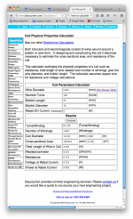
PS: After looking a bit harder, I found this coil properties calculator. Is it of any use in this case? [see attached image] This one also allow for inducance calculation on one of it's tabs.
Just to be clear on this: with "r" in rC and rCRC, you mean the internal resistances of the transformer secondaries and ESR in the filter caps?
Inputting the numbers you gave above:
C=80mF and t=160ms results in R=2 Ohms. That equates to a 12V voltage drop at full output. That is, ofcourse, unacceptable.
Given the nature of the UniversalPSU from the DIY-audio store, I would like to think that an rCRC option for my amp would exist. I just can't make the numbers work with the data discussed above. Do you know if I can simply swap out the Pi resistors for a coil in that psu design? It seems that it would solve a lot of problems in one blow.
Now, given a wire thickness, a number of windings and diameter, I should be able to calculate the inductance of the coil. I believe the formula for deriving the -3dB frequency of that CLC filter is more or less the same. But: am I correct when I say that this frequency is not that important? The most important task of the psu is voltage and current delivery; not so much HF suppression, although it's a nice added bonus.
Just to be complete:
Using this calculator for air-cored coil inductance, I found for a 150 turn, 2 winding coil with 0.9mm wire and inductance of 269uH.
Inputting that into f = 1/(2*PI()*SQRT(L*C)) and Z = SQRT(L/C) with my known capacitance of 80mF, I get f=34.4Hz and Z=0.058 Ohms.
PS: After looking a bit harder, I found this coil properties calculator. Is it of any use in this case? [see attached image] This one also allow for inducance calculation on one of it's tabs.
Attachments
Last edited:
- Status
- This old topic is closed. If you want to reopen this topic, contact a moderator using the "Report Post" button.
- Home
- Amplifiers
- Power Supplies
- Power Supply Resevoir Size