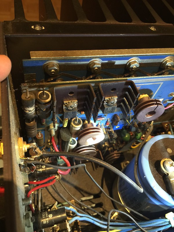
A friend gave me a Threshold 4000 that was in need of help. Both channels seem to be shorted. Here is the worst one.
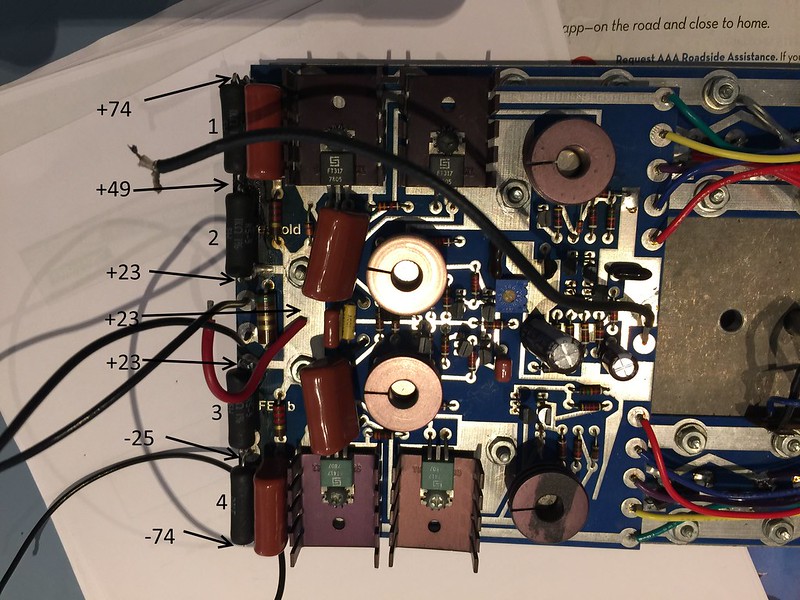
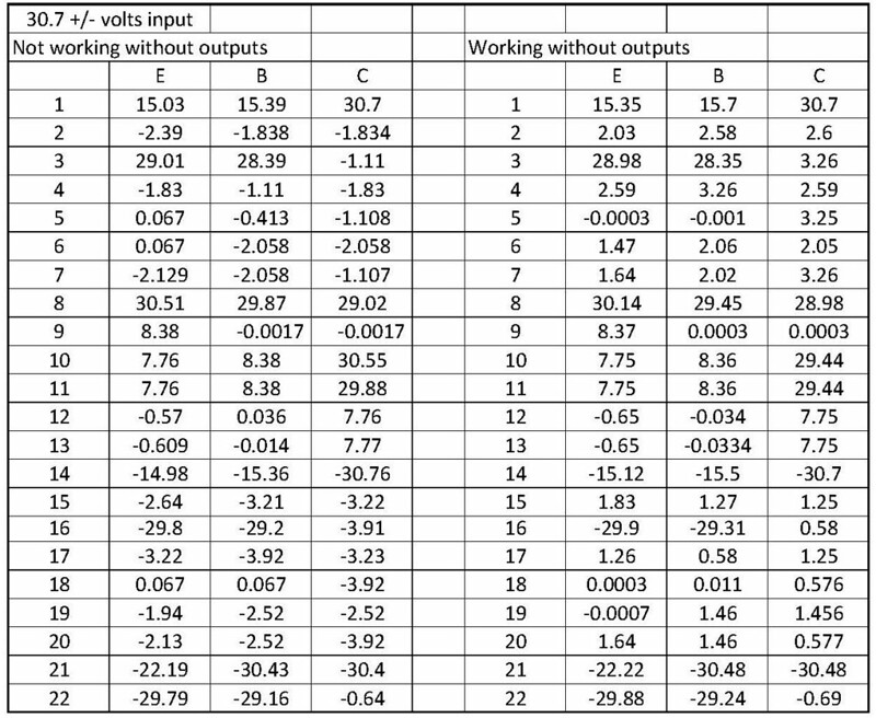
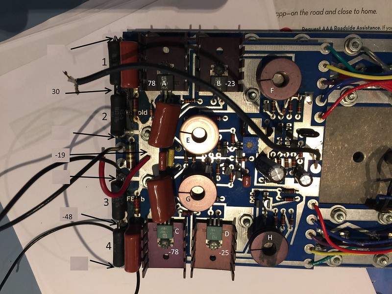
Jon at vintageamprepair.net help me with the output sub. Here it is back together. There is still something not right. See the voltages in the picture at 120volts input. The 1k resistors number 3 & 4 get hot pretty quick.
What should I check next?
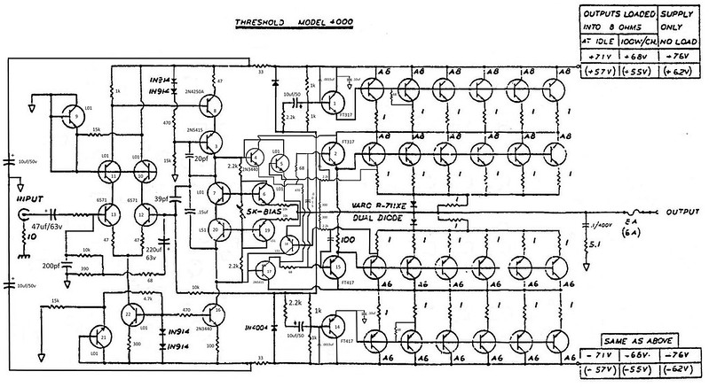
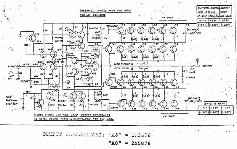
This schematic shows the differences I have seen on my board so far. I moved it here from post 17 so I can update it.
400
 Volts30 with working no outputs
 diode fixed
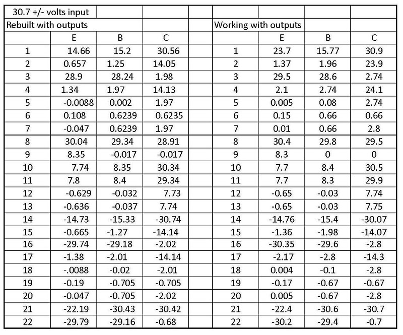 Volts30 with rebuilt
Jon at vintageamprepair.net help me with the output sub. Here it is back together. There is still something not right. See the voltages in the picture at 120volts input. The 1k resistors number 3 & 4 get hot pretty quick.
What should I check next?
This schematic shows the differences I have seen on my board so far. I moved it here from post 17 so I can update it.
400
Last edited:
I see you already replaced all tantalums
whatever , my usual procedure with amps that burned , is to check every resistor in situ; if I have some doubts in measurement , desoldering and lifting one end of resistor is enough to clear doubt .
same applies for diodes
also - fastest way is to , one by one, desolder each semiconductor , test it and put it back or replace , if bad .
A friend gave me a Threshold 4000 that was in need of help. Both channels seem to be shorted. Here is the worst one.
Jon at vintageamprepair.net help me with the output sub. Here it is back together. There is still something not right. See the voltages in the picture at 120volts input. The 1k resistors number 3 & 4 get hot pretty quick.
What should I check next?
The voltage at the joint of resistors No:3 and 4 must be same as above (49V) at the positive side.
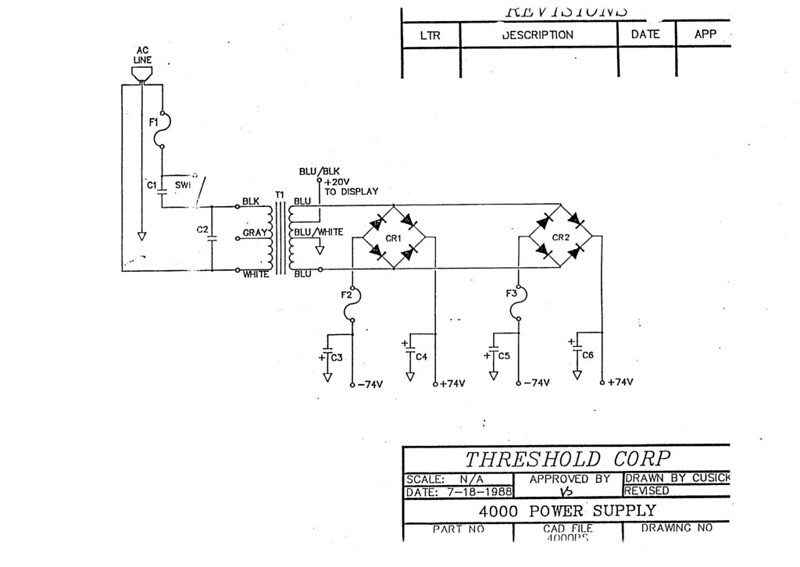
No power supply schematics ?
Where is that joint connected to ?
+23V must be 0 Volts (assuming it is connected tothe output through fuse).
Last edited:
It may not be systematic.
The positive and negative sides should have same resistance at quiescence in order to get a zero voltage at common line which is also output. But in his case, resistance of positive side is higher than negative. This may happen because of any part at upper or lower.
Anyway, in my opinion it is likely a bad one at upper side.
To localise it,
i would first disconnect the upper and lower power transistor blocks (A6-A8) from the rail voltages (+-74V) and re-check voltages. This will save him time.
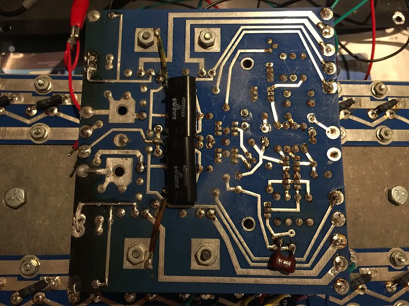
Here is the back side of the board.
And the power supply.
One goes to the collector of a FT317 and a 10uf cap to a 2.2k resistor to the output. The other to a FT417 and a 10uf cap to a 2.2k resistor to the output.
It is connected to the output.
I think I see this on the schematic but not on the board. This is a pc FE1b board.
And the power supply.
Where is that joint connected to ?
One goes to the collector of a FT317 and a 10uf cap to a 2.2k resistor to the output. The other to a FT417 and a 10uf cap to a 2.2k resistor to the output.
+23V must be 0 Volts (assuming it is connected tothe output through fuse).
It is connected to the output.
see at sch 1K and 1K5 (though - it would be good to recheck their position , it looks suspicious on pic ...... 1K5 inside , 1K outer - to rails)
I think I see this on the schematic but not on the board. This is a pc FE1b board.
I think I see this on the schematic but not on the board. This is a pc FE1b board.
I was a few post behind. I get it now. I went with what was in there before. This channel looks original. There are a number of changes on this one.
i would first disconnect the upper and lower power transistor blocks (A6-A8) from the rail voltages (+-74V) and re-check voltages. This will save him time.
This will be the next step. I need to put everything back on the board first. It may be the weekend before I get to it.
Thanks for the help.
Tony
This schematic shows the differences I have seen so far.
schematic
An externally hosted image should be here but it was not working when we last tested it.
schematic
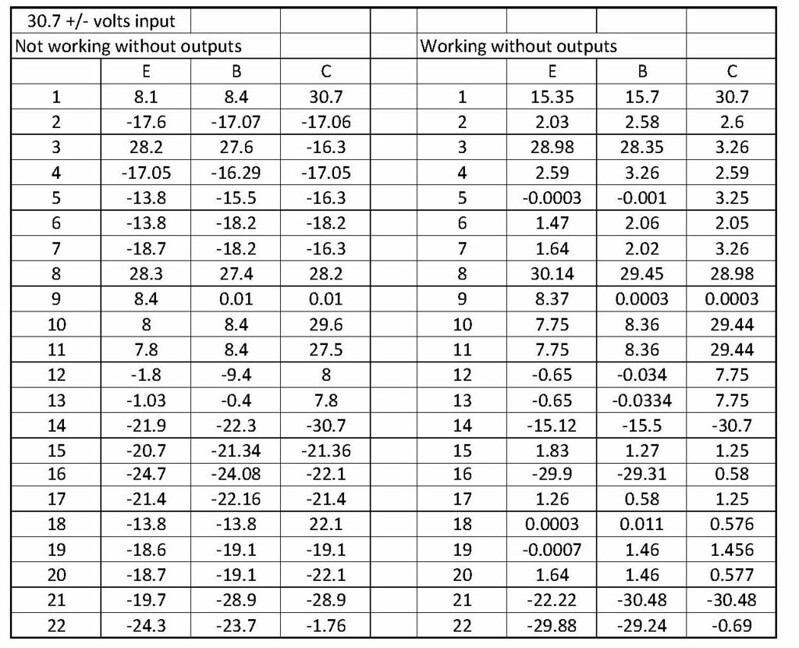
With power just going to the board and no outputs hookup I get this. Transistor B is -23volts. I have not had time to think about it yet.
 IMG_1949 volts no outputs
Last edited:
- Home
- Amplifiers
- Pass Labs
- Threshold 4000 repair. Need some help.