Listening with and without the cover on made a huge difference. Allowing sound at normal listening levels to have direct
access to the naked board really messed things up.
One more advantage of testing your gear with headphones. The environment plays a lesser role.
I think I read somewhere that TotalDAC has encapsulated resistors. This is probably not just for keeping things secret.
Simon,
You have misread re the TotalDAC resistors. It uses un-encapsulated//naked Vishay foil resistors without any kind of potting.
cheers
Paul
Last edited:
0,02.And your purchased product was?
0,05?
When one of the rcas came unplugged I discovered that the sub amp is introducing phase cancellation in its mono summing circuit.
Hello,
Reading all the stuff for a few days and for sure I'm really interrested by it.
Just wondering about some comments I read on listening impressions, and finally robertrowett's comment.
At least two indications that there might be a reverse phase on one of the outputs. The one above and also some listeners told that the sound was comming from left and right, nothing from the center.
Not sure of anything but that could explain a few things.
On another side, it looks so obvious that it's one of the first controls to be done as said Soren that I am almost embarassed to write that.
Tiny
R is 4990 Oh.How did you measure? "in circuit" and DAC not powered I suppose.
If you have a close look on the PCB, some of your assumptions on the topology seem not to be correct.
View attachment 471062
You see that "2R" is a 10k (103) with something big (47E) in parallel giving in total something slightly smaller 10k. The backbone of the ladder are the black ones with a resistance of around 5k.
2R is 9980. The switch have internal 13 Oh. Therefore the resistance has to be
9980-13 = 9967 Oh. = (10 K // 3.01 MoH)
If you draw two 24 R ladders in LTspice finished in a 2R. Measuring the impedance of any R 4990 Oh. will actually be 4890 because it has the rest of the circuit in parallel. So to measure the resistances 4990 "in circuit" and the DAC without power is not expected R 4990 to measure their value, theoretical in circuit 4890, but really 4893.5 because the mass to be added for some reason 3.5 Oh.
Last edited:
R is 4990 Oh.
2R is 9980. The switch have internal 13 Oh. Therefore the resistance has to be
9980-13 = 9967 Oh. = (10 K // 3.01 MoH)
If you draw two 24 R ladders in LTspice finished in a 2R. Measuring the impedance of any R 4990 Oh. will actually be 4890 because it has the rest of the circuit in parallel. So to measure the resistances 4990 "in circuit" and the DAC without power is not expected R 4990 to measure their value, theoretical in circuit 4890, but really 4893.5 because the mass to be added for some reason 3.5 Oh.
Two things that could inflouence due the position of the measured R resistor:
When I measured the resistance with my high precision bench top multimeter the values were fluctuating nonsense. With a hand held multimeter I got plausible measurements (~10k, ~5k). I think that is due to the influence that the capacitor at the end of the ladder. This influence increases as closer you come to the end of the ladder and could explain your variation.
Less likely:
If you measure while the DAM is not powered the shift register connected to the 2R has a high resistance, I did not find the value in its data sheet, but if it is not very very high you get also an effect through the 2R part and that would be dependent on which R-resistor of the ladder you measure.
Søren-
As a few people here are using this strategy I thought this would be an appropriate question for this forum.
I have been running my subwoofer amp from the Buffered outputs (SE- +/GND) and my main amp from the unbuffered outputs simultaneously. When one of the rcas came unplugged I discovered that the sub amp is introducing phase cancellation in its mono summing circuit.
If I reverse one of the buffered output connections on the board (+/GND to -/GND) will it fix the phase issue in the summing circuit?
Also- would this introduce crosstalk into the direct outputs or otherwise risk harming anything on the DAM?
I have no clue what "phase cancellation in its mono summing circuit" means. But whatever you connect to the buffered output will not affect the unbuffered output. The dam1021 outputs are also are pretty tolerant to whatever you connect, and the output buffers are short circuit protected.
Sebastian, have you had a chance, or do you have a capability with your system to listen unbuffered output? If you have not had a chance please try you might like it.
On another note, I think we are all too serious about $ 230 DAC with many benefits and seriously great potential. Initial simplicity is the absolute advantage allowing to have it up and running in no time and almost without any further investments. I hope to see major upgrades in near future that will improve over alrady excellent DAC
Agree with that!
i tried DAM because of its ability to flash the firmware and nearly all in one design
I have no clue what "phase cancellation in its mono summing circuit" means. But whatever you connect to the buffered output will not affect the unbuffered output. The dam1021 outputs are also are pretty tolerant to whatever you connect, and the output buffers are short circuit protected.
Good to know I won't ruin the board this way. Here's the situation: when I connect the buffered outputs via + and ground as described on hifiduino blog I send left and right se signal to the stereo inputs of my sub amp. The amp puts out mono like most of them do. I assume that since the bass is fuller and more accurate with only one stereo channel connected that there is a problem with combining the signals somewhere. Phase cancellation is my guess. i did not assume an engineering error, but user error. So again: is it correct to hook up the buffered outputs for se signal as hifiduino shows?
Søren,
is there any approximation of jitter level on the I2S input, beyond which the DAC performance starts to suffer? How much will it tolerate?
Can we say the USBstreamer's 2.6 ns peak-to-peak is in the safe area?
is there any approximation of jitter level on the I2S input, beyond which the DAC performance starts to suffer? How much will it tolerate?
Can we say the USBstreamer's 2.6 ns peak-to-peak is in the safe area?
You can power a relay from one of the 7V transformer windings. Just a small diode bridge into a capacitor of say 470 uf, then a resistor to the positive relay terminal. Put 1000uf across the relay. Put another diode 1n4007 or similar across the resistor pointing cathode back to the bridge.
If you use a 5v relay, and choose a resistor that works with that and your rectified supply, you will get a delayed turn on and very quick turn off.
Use the relay contacts in series with the signal or shunt.
Updated:
You can power a relay from one of the 7V transformer windings. Just a small diode bridge (1242-1245-ND) into a capacitor of say 470 uf 25V (493-1064-ND), then a resistor to the positive relay terminal. Put a 1000uf 25V capacitor (493-5913-1-ND) across the relay's coil terminal.
If you use a 5v relay from Digikey (255-1062-ND), and use a 180R .25W resistor you will get the turn on and turn off that you need.
Use the relay contacts in series with the signal or shunt.
Part numbers in brackets are Digikey part numbers.
Last edited:
I had only 23 R in my ladder LTspice scheme. Now with 24 R all change. In parallel with R is 255K. In this case the value to measure would be 4994 Oh.Two things that could inflouence due the position of the measured R resistor:
When I measured the resistance with my high precision bench top multimeter the values were fluctuating nonsense. With a hand held multimeter I got plausible measurements (~10k, ~5k). I think that is due to the influence that the capacitor at the end of the ladder. This influence increases as closer you come to the end of the ladder and could explain your variation.
Less likely:
If you measure while the DAM is not powered the shift register connected to the 2R has a high resistance, I did not find the value in its data sheet, but if it is not very very high you get also an effect through the 2R part and that would be dependent on which R-resistor of the ladder you measure.
And assuming an shift register impedance 600 MOh. The theoretical measured impedance would 4993.5 Oh.
Everything is in tolerances.
")
Except the first ten 2R. And the effect of lower resistance near the exit. May be near the condenser.
Attachments
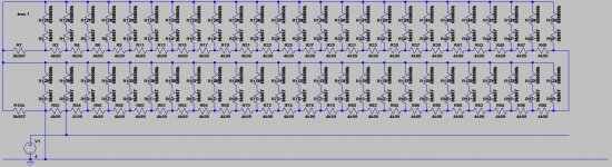
I had only 23 R in my ladder LTspice scheme. Now with 24 R all change. In parallel with R is 255K. In this case the value to measure would be 4994 Oh.
And assuming an shift register impedance 600 MOh. The theoretical measured impedance would 4993.5 Oh.
Everything is in tolerances.
Except the first ten 2R. And the effect of lower resistance near the exit. May be near the condenser.
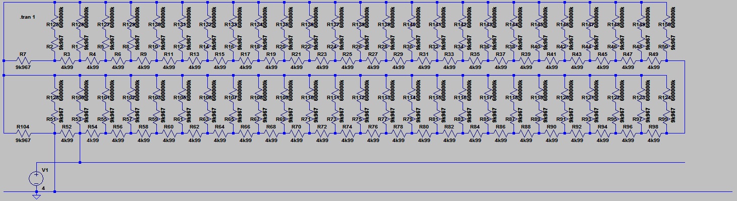
The output end of the ladder is to my opinion like that:
After the ordinary ladder (25 2R to shift register and 24 R backbone)
you have
a 13R (130) from backbone to output,
a R from shift register to output (for second last most significant bit),
two R in parallel from shift register to output (for the most significant bit),
It is a 28 bit sign magnitude DAC, so 1 bit sign (pos or neg ladder) and 27 bits magnitude in each ladder.

I'd be willing to bet that what you like about the total dac is due to its triode buffer. Put a triode buffer on the dam , don't use the opamps and I think you might be surprised. And use a decent set of speakers that reveal imaging, soundstaging and the other things that make music more believable.
The TotalDac I've heard doesn't have a tube output. Neither did my Monica.
I'm already alternating between the buffered and the unbuffered output on the DAM.
The output end of the ladder is to my opinion like that:
After the ordinary ladder (25 2R to shift register and 24 R backbone)
you have
a 13R (130) from backbone to output,
a R from shift register to output (for second last most significant bit),
two R in parallel from shift register to output (for the most significant bit),
It is a 28 bit sign magnitude DAC, so 1 bit sign (pos or neg ladder) and 27 bits magnitude in each ladder.
Maybe I should tell that it's actually what's called a segmented DAC, it consists of the 1 bit sign, a 2 bit unit element (also called thermometer) section for the two MSB bits, and a 25 bit R-2R section for the rest, totally 28 bits.
Thanks, finally I understand what is a 28 bit DAC sign magnitude. The theoretical measures do not change.The output end of the ladder is to my opinion like that:
After the ordinary ladder (25 2R to shift register and 24 R backbone)
you have
a 13R (130) from backbone to output,
a R from shift register to output (for second last most significant bit),
two R in parallel from shift register to output (for the most significant bit),
It is a 28 bit sign magnitude DAC, so 1 bit sign (pos or neg ladder) and 27 bits magnitude in each ladder.
View attachment 471214
The TotalDac I've heard doesn't have a tube output. Neither did my Monica.
I'm already alternating between the buffered and the unbuffered output on the DAM.
From Feb 7th, back when I thought you might actually be interested in tuning the sound of the DAM...
Sebastian,
Perhaps this is in part due to the opamp output stages on the DAM1021? Your appear to have a predilection for valves and transformers. The Monica Discrete uses output transformers and the Totaldac uses discrete class-a buffers. You might find that an output trafo adds enough of what you like?
cheers
Paul
Last edited:
Maybe I should tell that it's actually what's called a segmented DAC, it consists of the 1 bit sign, a 2 bit unit element (also called thermometer) section for the two MSB bits, and a 25 bit R-2R section for the rest, totally 28 bits.
Analog devices has very nice tutorial on segmented DAC's...
http://www.analog.com/media/cn/training-seminars/tutorials/MT-016.pdf
- Home
- Vendor's Bazaar
- Reference DAC Module - Discrete R-2R Sign Magnitude 24 bit 384 KHz