You need one LVDS receiver.
The only one I found with same pinout is this I2S‚Æ�AI2S‚à‚Ç‚«‚Æ�A S/PDIF‚ɂ‚¢‚Ä
Another receivers with different pinout are. Perhaps would be possible to modify it.
Aune kit Module d'entre HDMI vers I2S - Audiophonics
ºÍ§Ó*µ响
K&K Audio | Digital Audio
Also you can use The Teleporter with modifications
Teleporter Digital Transfer Module
A good solution may be to replace the HDMI connector of Audiophonics receptor, for which you already have.
Regards
Thanks alot for your information.
In addition to this.
Do you think this can be used?
HiFimeDIY i2s/DSD Isolator 384kHz HDMI to TTL interface
Its got the same receiver that the fidelix type has. And the fidelix hdmi transceiver module has the same tranceiver that the gustard u12 have.
Thanks in advance.
If it have the same pinout of your Gustard, is perfect.
Regards
Hi Paul,I've been having a play with creating something close to the Ayre MP Listening position filter described in their MP white paper.
I've used a similar method to POS in that the main filter is minimum-phase, but an additional linear-phase filter is used to control the cutoff slope.
As per the Ayre white paper this filter is -6dB at 22050hz, and -96dB at 44100hz. I'm sure this will give Søren the horrors, but I feel if it's good enough for Charles Hansen to include in a commercial product as the preferred setting it can't be all bad
I've included comparison with POS's filter (pos - blue, my "MixPhase1" filter - red).
Filter Response showing the slower roll-off, and earlier onset of filtering. It's about -1.2dB at 19kHz, so not as ruler flat as POS or stock filters.
IR showing 2, possibly 3 post-ringing cycles on the MP1. Not as good as the 1, possibly 2 cycles of the Ayre. Both POS's filter and my MP1 have a minimal amount of pre-ringing from the use of linear-phase filters.
Step response is similar story to the IR.
How does it sound? I like it, but them I'm biased (and possibly have tin ears).
zipped .skr with MixPhase1 at 44.1 position attached.
Great work!
Have you tried implementing the so-called "apodizing" reconstruction filter that was all the rage among audiophiles a few years back?
The idea is to "hide" the time-domain effects of the successive reconstruction filters that the signal might have encountered during its production (ADC, resampling, etc.).
So as those filters must have a knee (and associated (pre)riging) around 22050Hz the idea is to be already down quite low (-20dB maybe, or even less?) at that frequency, and of course only use minimum-phase filters (at that frequency point at least).
Of course this implies cutting edges on the response up high, but this makes sens to use with "bad" recordings using bad filters (like the ones either recorded or "remastered" in beginning of the digital era...).
I think it would be best if Soren could implement a "preset" system, similar to the ones we see in some commercial DACs, to let the user choose and change filters almost "on the fly".
Of course the DAC needs to have a "flat" filter (within 0.5dB at 20kHz), and then other more shallow filters.
Regarding the 48kHz filters, you can directly use the 44.kHz one (I mean the generated coefficient, and let the DAC to the convolution at a higher rate), and same goes for 96 vs 88.2, etc.
Oh and by the way, please write either "pos" or "Pos" instead of "POS", as this one really sounds like the well known infamous acronym...
")
Last edited:
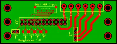
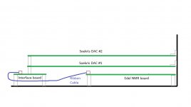
I plan to purchase a Soekris DAC (or two) shortly and have started to work out my implementation. The DAC will be used within a network renderer, using as the I2S source either an Edel NMR or a Beaglebone Black running the miero Botic Linux distribution, so no interest in Toslink or SPDIF.
In addition, I want to make use of J2 for power input (as per HiFiduino) to bypass the bridge rectifier with screw down terminal blocks for connections.
I'm also interested in the possibilities of using two DACs with crossover filters.
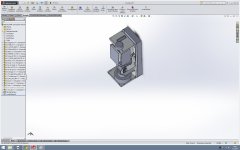
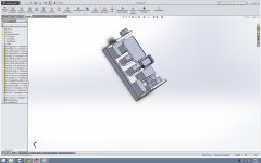
I've designed my own little interface board to get I2S and power to the DAC(s). It is designed to stack onto the DAC board headers. The attached diagrams show the board and how I am thinking of using it. Thanks to Enrico for his help.
Unfortunately I haven't seen any information on the coordinates of J2 and J3 on the Soekris board so I have placed them by fitting a copy of the mechanical drawing on the hifiduino page to an outline of the DAC board. Hopefully I'll be able to refine placement if necessary.
I'll probably get a small batch of boards made so if anyone is interested....
Ray
In addition, I want to make use of J2 for power input (as per HiFiduino) to bypass the bridge rectifier with screw down terminal blocks for connections.
I'm also interested in the possibilities of using two DACs with crossover filters.
I've designed my own little interface board to get I2S and power to the DAC(s). It is designed to stack onto the DAC board headers. The attached diagrams show the board and how I am thinking of using it. Thanks to Enrico for his help.
Unfortunately I haven't seen any information on the coordinates of J2 and J3 on the Soekris board so I have placed them by fitting a copy of the mechanical drawing on the hifiduino page to an outline of the DAC board. Hopefully I'll be able to refine placement if necessary.
I'll probably get a small batch of boards made so if anyone is interested....
Ray
Attachments
Ray, it looks nice - but didn't Sören say to not power the boards through the J2 connector?
I didn't see Soren say not to use J2 but having just quickly checked the hifiduino site I see the information has disappeared so it looks like you might be correct. I wonder why you can't use J2?
Should be easy enough to route the power to a J1 header if necessary. Would be good to have a full mechanical drawing so I can position the header correctly.
Ray
Ray
see post 1633
interesting system you are putting together
Best
Bob
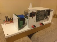
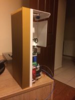
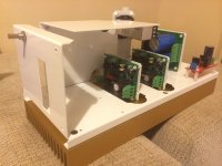
Almost nobody send build pictures, they are so important less experienced builders like me.
Here is my setup;
SDTrans384 (Not arrived yet)
Acko regulated power supply for sdtrans384 (i will seperatelly power the board with 1.2v 3.3v and 2.5v(Not arrived yet) i also planing to use 3.3v to power up i2s on Soren R-2R.
diyinhk 5v regulator for sdtrans384
Soren R-2R
Neurochrome Modulus-86 stereo amplifier and supply board.
Do not know which cables types to use yet.
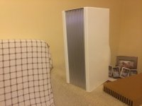
Almost every hifi design is horizontal so i decided to build a vertical one.
I am working in a case manufacturer so my mechanical capabilities almost limitless
Whole body made from 1.5mm aluminum.
i like gold colour so i made gold like eloksal coating on aluminum heatsink it will be a good buddy with white body. Some of the componenets are so close eachother but it is just a prototype, i can totally change the design according to your welcome comments.
Here is my setup;
SDTrans384 (Not arrived yet)
Acko regulated power supply for sdtrans384 (i will seperatelly power the board with 1.2v 3.3v and 2.5v(Not arrived yet) i also planing to use 3.3v to power up i2s on Soren R-2R.
diyinhk 5v regulator for sdtrans384
Soren R-2R
Neurochrome Modulus-86 stereo amplifier and supply board.
Do not know which cables types to use yet.
Almost every hifi design is horizontal so i decided to build a vertical one.
I am working in a case manufacturer so my mechanical capabilities almost limitless
Whole body made from 1.5mm aluminum.
i like gold colour so i made gold like eloksal coating on aluminum heatsink it will be a good buddy with white body. Some of the componenets are so close eachother but it is just a prototype, i can totally change the design according to your welcome comments.
Attachments
Last edited:
I plan to purchase a Soekris DAC (or two) shortly and have started to work out my implementation. The DAC will be used within a network renderer, using as the I2S source either an Edel NMR or a Beaglebone Black running the miero Botic Linux distribution, so no interest in Toslink or SPDIF.
In addition, I want to make use of J2 for power input (as per HiFiduino) to bypass the bridge rectifier with screw down terminal blocks for connections.
Ray
I've been thinking about the BBB/Botic system also, ideally with two dams to go balanced raw out. My understanding was that 12v was the optimum DC voltage. I'll be using a Phoenix screw down block for dc in, which will mean leaving the on board diodes in circuit-- but I don't see a downside to this. What are the potential negatives of having the superfluous diodes there?
I cannot imagine a superfluous rectifier bridge to be benign.
I would also think a good stiff non-regulated supply would be better than having cascaded regulators - there are already regulators feeding regulators in the circuit. When you think of them as filters you realize that a haphazard string of them can do harm.
I would think a simple supply using a pair of slightly over-rated (VA) transformers with a choke in between two caps, along with your favorite rectifier of the moment. I would think using a little higher voltage transformer than you first might have considered and then a small film cap (1 to 2 uf) as an input cap would work very well.
Consider some of the low voltage CREE SICs.
You will need to tune it to get on the money for the voltage. Bleeders come in handy for this. Bleeding away extra voltage usually results in a better supply.
This is my plan along with replacing the caps at the 5 volts reg with A123 batteries and at the output of the 3.3 volts reg. You will need to keep the thing on all of the time unless you put in a switch to turn the batteries off when you want to turn it off. In progress ... Consider the batteries as being charged by the regulators and the batteries being extremely low ESR power supplies to the circuits they supply. The existing circuits will maintain the charge on the batteries.
ANR26650M1B Cell
One will have to use two 3.3s in series to get the five volts. Making sure the voltage has been depleted to 5 volts for each series pair before installing.
Easy enough to add a simple switch at ground to turn them off.
Starting off with it as specified to make sure it is working and then proceeding with the fun and games.
I Repeat:
I can only recommend to supply any power on J1, the diode bridge used on the input is a low noise schottky type.
J2 is NOT for supplying power, it's for testing or for sourcing small amount of power for external input circuits. Applying power will probably blow the board.
If you insist to improve the onboard power supply, try replacing the 6 electrolytic capacitors with aluminum polymer types, 1000u 16V exist in same 10mm smd footprint and t.ex. digikey stock them at $2.20 each. Should be easy to replace.
You can also add a small polymer electrolyt on the 3.3V output, but please note that the clock oscillator power already have a filter, so I doubt it will make any difference.
But on the other hand, just go ahead, I'll be happy to sell you a couple of new boards
Last edited:
Hi Soren,
Are the plastic smd caps glued on the pcb ? Easier to cut the leads near the body cap to remove the caps then after remove with flux the leads staying on the pcb ?
I really believe people should wait the benchmark between handmade filters before trying hard tweaks ! Than maybe after many listenings, some changes if it's not enough in the FGPA strategy made by Soren himself.
ANd this is a an addict to caps tweaking who's saying that !.
Bah everyone is free but hard to testimonial about filter improvement if everyone is changing first the layout !
Two cents.
Are the plastic smd caps glued on the pcb ? Easier to cut the leads near the body cap to remove the caps then after remove with flux the leads staying on the pcb ?
I really believe people should wait the benchmark between handmade filters before trying hard tweaks ! Than maybe after many listenings, some changes if it's not enough in the FGPA strategy made by Soren himself.
ANd this is a an addict to caps tweaking who's saying that !
.Bah everyone is free but hard to testimonial about filter improvement if everyone is changing first the layout !
Two cents.
Hi, I recently purchased a .001% board but am waiting to start the build until I have a better understanding of how to make firmware updates and incorporate new filters.
I've noticed a few people have found single ended performance to be superior to balanced output. I'm wondering why this may be. Please share if you know of a reason why.
Also is there an easy way to bypass the output buffers of the balanced outputs -- to output directly from the resistor ladder in balanced operation?
- Home
- Vendor's Bazaar
- Reference DAC Module - Discrete R-2R Sign Magnitude 24 bit 384 KHz