i'm just trying to find out if either approach (in /out) has any advantage/disadvantage with respect to cooling.
The only way you can make a general statement of which is better is if you have a known configuration for which you know all the details and where the fan is to be mounted and even the fan performance characteristics. As others have said you want airlfow. Best not to work against natural convection, think about what happens when the fan/heatsink gets dirty, etc...
Intuitively, I see it as this:i'm just trying to find out if either approach (in /out) has any advantage/disadvantage with respect to cooling.
Since the heatsink is solid, air can only be pulled around it.
But air can be pushed directly onto the heatsink. Hence, more efficient.
But I agree with RonE. I've seen some amps here with a tubular-type heatsink, with the fan on one end. I wonder how the above compares with that configuration; it seems airflow & surface area would be equal either way.
Pplease read here. He explained why blowing air onto heatsink is better than sucking.
ESP - Heatsink design and transistor mounting
Refer para 18.
ESP - Heatsink design and transistor mounting
Refer para 18.
I've heard that fans usually blow air OUT of a box so that the heat the fan adds to the air doesn't add to the heat INSIDE the box. OTOH, fans rarely add anywhere near as much heat to the air as does whatever else is in the box, so this may not be significant.what approach is better when fan cooling?
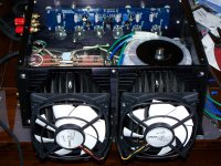
make the fan blow into the enclosure or out?
Last edited:
Both are all right as long as you consider:
1. An inlet filter. When you suck air through the heatsinbk generally air (and dust) creeps in from every available crevice and this ends up in a very messy case. With a single inlet fan and a nice large inlet with a filter, there is one major air path and all the others are actually pushing air out rather than in. In the PC world, this is referred to (somewhat incorrectly) as positive pressure and results in mildly higher temperatures but better dust control. The other way, with one exhaust and many tiny inlets (some invisible till they get dusty) is the 'negative pressure' case.
2. Your fin pattern supports the kind of method you are using and the predicted airflow path within the case. For example, having vertical fins ends up being useless unless you have an amp that has the fan at the bottom or top of the case (which would be highly unusual, as most forced cooling tunnels are horizontal to prevent the amp from heating up other components in a vertical racking unit).
3. Airflow is equal on both sides of a fan, but the air pressure is not. Usually fans have more pressure at the outlet side than the inlet side. Again, heatsink layout within the case and the placement of the fan have a great deal to do with how weel each works for you.
4. Once inside a case, a fan blowing on to the heatsink will basically be pushing a lot of hot air around the case and heating up other components. This is one reason for exhaust-only solutions having better temperatures in almost all cases except the most messy builds. This is something to account for when planning the layout.
Basically, both will work out equally well. For open builds I would prefer moving air on the sink, but for closed ones either a tunnel or exhaust-only solution would probably work better.
Read https://tetech.com/wp-content/uploads/2013/10/ICT2000TMR.pdf gives some rather more studied results. And also gives a measure of the scale of difference FOR THE HEATSINKS USED. As I said before, for the gentle stirring generally needed for DIY Not really worth worrying about.Pplease read here. He explained why blowing air onto heatsink is better than sucking.
ESP - Heatsink design and transistor mounting
Refer para 18.
For a case rather than a heatsink I stand by the fact that you fit an exhaust fan before you fit an inlet fan as you get a more even airflow and the secret still is to run it as slowly as you can to keep noise down.
and the secret still is to run it as slowly as you can to keep noise down.
You can pick up almost silent PC fans these days.
We designed a +12VDC temperature-controlled fan into a deskside computer, in the previous century. It used a 10Kohm @ roomtemp NTC thermistor to sense temperature, and a linear circuit to vary the voltage across the fan.
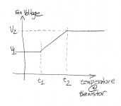
A circuit like this has three degrees of freedom; three independent knobs that the "designer" (actually, the marketing department) can adjust however he wishes. Diagram below.
t1: the "too cold" temperature. If temp < t1, the fan runs at min-fan-voltage. DC fans stall and poop out at low voltage!
t2: the "too hot" temperature. If temp > t2, the fan runs flat out at Vfan = Vcc.
v1: the min-fan-voltage. DC fans generally don't start / don't run with v < Vcc/2
"v2" in the diagram, is the max-fan-voltage, which is Vcc. Which is 12 Volts for a 12VDC fan.
Of course the advantage is, the fan only runs as much as needed. It's as quiet as possible.
You do need to choose a good spot to place the temperature sensor (thermistor). Obviously.
Here are a bunch of 10Kohm, NTC thermistors that would be candidates for the thermal sensor.
Today, of course, people would use a DS18S20 temperature-to-digital sensor IC, a 99 cent microcontroller, some PWM software, and an Nchannel power MOSFET to implement a temperature controlled fan. Slightly higher parts cost (the Dallas Semiconductor temperature sensor ain't cheap) but dramatically smaller parts count. Yes indeedy. But. But! But who wants to put, gasp!, digital electronics into an audio product?? Wharrgarbl, high speed edges, EMI, ground noise, wharrgarbl! Oh the humanity.
Attachments
arrghhh now i'm more confused!
i guess i'll have to try both to see if i can detect or measure any appreciable difference.(Mr Elliot's article from the ESP pages presents a strong case but the other linked article seems self contradicting)
seems waste heat is fact of life in power electronics.
would using something like "peltier junctions" attached to heatsinks provide enough power/heat recovery to run stirring /cooling fans at a level that would be effective?
would using something like "peltier junctions" attached to heatsinks provide enough power/heat recovery to run stirring /cooling fans at a level that would be effective?
Nope, no chance at all. Luckily fans for the sort of application you are looking for need very little power.
would using something like "peltier junctions" attached to heatsinks provide enough power/heat recovery to run stirring /cooling fans at a level that would be effective?
Peltiers have terrible efficiency, about 20% IIRC. So if you remove 60W of heat you'll have to burn 300W in the Peltier to get the same temperature on each side.
Also Peltiers then need to be cooled to have maximum 30 degree difference between the two sides. Which is pretty much what you shoot for to begin with, even for hot Class A designs...
Don't see the point myself, peltiers are recommended for use where you need sub-ambient levels of cooling in a cheap and easy manner.
Last edited:
There's nothing you can achieve with peltiers, water cooling and fans that you can't achieve with bigger heatsinks and/or more output devices. ") An audio amp is not like a computer CPU where all the heat comes from a single silicon chip of limited size. The die area (and resulting junction-to-case thermal resistance) of an audio output stage is just another variable that you can play with.
An audio amp is not like a computer CPU where all the heat comes from a single silicon chip of limited size. The die area (and resulting junction-to-case thermal resistance) of an audio output stage is just another variable that you can play with.
An audio amp is not like a computer CPU where all the heat comes from a single silicon chip of limited size. The die area (and resulting junction-to-case thermal resistance) of an audio output stage is just another variable that you can play with.
Last edited:
- Status
- This old topic is closed. If you want to reopen this topic, contact a moderator using the "Report Post" button.
- Home
- Design & Build
- Construction Tips
- fan cooling