Those are RFI filter capactiors as described in the apnotes for the THAT parts. The green PCB's are back to back depletion mode mosfets for the input protection and an additional common mode filter for the isolated converter.
When using this interface with a juli@ soundcard the 1Vrms out @ FS really puts a limit on the usable dynamic range. So I removed D10/D12 so I can get a larger output voltage swing before clipping. (I will probobly increase the diode stack to still get protection just at a level more suitable for the juli@)
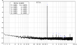
Unfortunately this puts the meter out of range but look at the performence I get when measuring one "mikevich" <0.00001% 1kHz oscillators of ebay
This is with the soundcard interface at the 200mV setting and the oscillator set for about 0.6V
Hi,
Can you provide more info on the mosfet boards? Also, you have R11 connected to C3? What changes were made to the fuse area? What would you ideally replace D10 and D12 with?
Thanks
I put one of these together recently, but due to the high nose floor I opted to just use some attenuator boxes I put together instead as they offered better performance. If I could get this as quiet as you have, that would change things. Thanks.
See here :
http://www.diyaudio.com/forums/tube...nterface-ideas-suggestions-8.html#post3945284
Other methods are also discussed in that thread like replacing the 49.9k resistors with bulbs.
See here :
http://www.diyaudio.com/forums/tube...nterface-ideas-suggestions-8.html#post3945284
Other methods are also discussed in that thread like replacing the 49.9k resistors with bulbs.
Thanks for the link, I missed that. If you don't mind the questions, why does it look like you have R13 connected to C3? Also what would you replace D10 and D12 with ideally?
SY, can you post loop back measurements or shorted inputs?
Would like to see what improvements you got.
I'll see what I can do.
Thanks. If possible, it would be nice to see what the battery does to ground loops, which I suppose is the biggest advantage of the battery supply.I'll see what I can do.
I.E., my request for loop-back or shorted inputs may not tell the whole story.
Thanks. If possible, it would be nice to see what the battery does to ground loops, which I suppose is the biggest advantage of the battery supply.
Exactly the case- it makes measurement setup much faster and more certain.
Swapping out the 49.9k resistors to incandescent lamps made a huge improvement. Powering off batteries not so much, it seems my USB source is doing OK.
Able to measure down to 0.0005% THD on the 200mv setting now with the D10 and D12 diodes disconnected. A loopback of my soundcard can manage 0.0003% THD.
Able to measure down to 0.0005% THD on the 200mv setting now with the D10 and D12 diodes disconnected. A loopback of my soundcard can manage 0.0003% THD.
Last edited:
That looks very good NYT. Have you looked at sines at lower and higher frequencies?
For example I like to check at 40Hz, 110Hz and 5KHz. Just a set of frequencies that I like to check because they sometimes turn up differences.
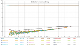
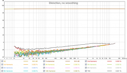
Looks good all the way through. Can't get measurements like that with D10 and D12 in place though :/ Without that, the interface loses a bit of its benefit. This is using a 2i2 for audio interface.
SC loop
SC + IF loop
Attachments
Last edited:
rat shack #7219 micro lamp...
Not sure how suitable they are, but they were the first ones I tested.
120v 60ma
http://www.radioshack.com/12v-microlamps-2-pack/2721092.html
Not sure how suitable they are, but they were the first ones I tested.
120v 60ma
http://www.radioshack.com/12v-microlamps-2-pack/2721092.html
Last edited:

I suggest that instead of removing D10/12, D11 / D12 be replaced by a string of 1N4148 diodes the number of is suitably selected to put the protection limit closer to the full scale voltage of the soundcard YOU are using.
Note: I got better THD (flatter increase) vs frequency by using THAT parts for the line recievers/drivers) (see posts a few pages back)
Note: I got better THD (flatter increase) vs frequency by using THAT parts for the line recievers/drivers) (see posts a few pages back)
Some of the added distortion will be due to the variable reverse junction capacitance of the diodes across the input lines.
Doubling up the diodes will halve the capacitance, if the voltage across each diode remains the same.
But what effect will the halved voltage have on the diode capacitance?
I have seen diodes in series with very low voltage Zeners, presumably to increase the reverse voltage capability, but also gains from the series capacitance of the two types of diode.
Is the added distortion when diodes are in place, in part due to high source impedance?
Zero source impedance should give zero added distortion when the diodes are in place.
Very low source impedance may show as lowered distortion. Can you test this?
- Home
- Design & Build
- Equipment & Tools
- Test & Measurement interface for Soundcard