RE: Crossovers, have you seen this from KEF:
http://www.kef.com/uploads/files/en/kef_topics/KEFTOPICS_vol4no2_crossover filters.pdf
http://www.hifiloudspeakers.info/Anatomy/KEFDocuments/KEFCS1A/KefSpec.gif
http://www.hifiloudspeakers.info/Anatomy/KEFDocuments/KEFCS1A/KefCross.gif
This is from the time when KEF started computer optimization, do they
sound better? I don't know.
Do you have the correct driver spec. versions? You'd have to check.
Sorry, but these images are not availible for all:
-------------------------------------------------------------------------------------You don't have permission to access /Anatomy/KEFDocuments/KEFCS1A/KefSpec.gif on this server.
Additionally, a 404 Not Found error was encountered while trying to use an ErrorDocument to handle the request.
As PB2 wrote... mostly as I have some KEF T27 & B110 drivers in KEF Concerto cabinets. I am in the process of preparing to fit new crossovers from Falcon Acoustics, rewiring, & bi-wire terminals. ...
It looks like the LS3/5A cab with its thin wall and dampening is taking the right approach. ...
this depends on what drivers you have. Early Concertos were build with B110A6362 and T27A6364. Only the last versions (Concerto SP1006) do have the right systems to build a CS1a (B110SP1014/T27SP1032).Do you have the correct driver spec. versions? You'd have to check.
Construction sheets you will find here (Post #172). But I think you saw this when following the whole thread.
I have build them for my own and they sound great. But only if you place them in the right position (not to far from the walls) and room (about a max. of 16m²).
Sorry, I ment a B110SP1003. There never had been a 1014 for B110 but for B200 (used in Chorale)CS1a (B110SP1014/T27SP1032).
RE: Crossovers, have you seen this from KEF:
http://www.kef.com/uploads/files/en/kef_topics/KEFTOPICS_vol4no2_crossover filters.pdf
http://www.hifiloudspeakers.info/Anatomy/KEFDocuments/KEFCS1A/KefSpec.gif
http://www.hifiloudspeakers.info/Anatomy/KEFDocuments/KEFCS1A/KefCross.gif
This is from the time when KEF started computer optimization, do they
sound better? I don't know.
Do you have the correct driver spec. versions? You'd have to check.
Seems that you have to go though the main page to get to those .gifs:
Item Description: KEF Electronics Brochure - Part No SL353 EN01
The literature supports David and Oliver in that quieting a box at frequencies below about 500 Hz calls for stiffness to push the resonances above this frequency, and at higher frequencies around 1 kHz it should be less stiff and very lossy (damped) to stop the sound transmission. Also agree that high damping is needed to suppress the cabinet's output at critical frequency where the panel resonates, and David commented on as being near transparent if there is no damping.
So undamped heavy walls alone are worse than light damped walls in the mid range and above.
However, this is an incomplete assessment. The Harwood curves are not a complete or up to date set of targets when assessing resonance audibility. I don't agree that we can use Hardwood to excuse significantly more resonance in the lower frequencies, and therefore justify a light/damped wall approach as the best solution. Harwood didn't have the benefit of the knowledge from numerous studies since then.
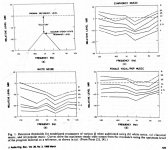
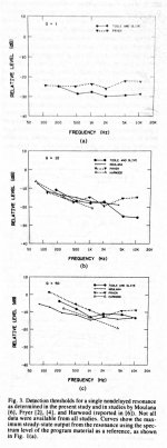
In "Modification of Timbre by Resonances: Perception and Measurement", Toole and Olive determine the audibility thresholds of resonances of various Q over frequency, and compare their results to Harwood and other earlier studies. I've attached some of their results along with outcomes from Fryer.
They show that higher Q resonances can have significantly higher levels before they are audible, compared to lower Q resonances. They explored this exhaustively with music, white noise, pink noise, and also looked at the impact of room reverb vs headphones. The findings were pretty consistent. So by increasing loss through adding damping, this decreases Q and you need to suppress the resonance peak level (which damping will do) more thank at high Q to make it inaudible for a given frequency. Olive found a rough figure of merit that each halving of resonance Q requires an approximate 3 dB reduction in level to maintain the same detection threshold. So the point here is that a higher resonance peak can and will be OK (within limits) if its a higher Q.
Olive and Fryer and others were also a bit less charitable than the BBC, the BBC allowed relatively higher low frequency resonance before audibility than any of the other studies.
So I think there are others ways to skin this cat.
Resonance frequency can also be increased by bracing, which makes the panel appear smaller. It doesn't have to be through panel composition alone. So, using mass to control low frequency resonance and significant bracing to push up the critical frequency seems to me the best approach. Damping can then be used to trade off Q vs level.
As posted earlier, the internal box absorption significantly lowers air borne excitation at upper mids and this can't be ignored. I reread the Harwood paper and it doesn't appear as if any filling material was used in their tests so this factor wasn't included. By having less airborne excitation, there is less resonance excited. Pushing the critical frequency into a frequency where the box is highly absorptive will show much better results in suppressing airborne resonance than the examples in the Harwood study.
There is still the issue Oliver mentioned of structural coupling through the driver frame, but this can be reduced through decoupling mechanisms:
https://www.google.ca/url?sa=t&rct=...=tUdvYod_l_zvYnZDtr12CA&bvm=bv.82001339,d.aWw
So I dispute the Harwood results are the last word. I think its more than feasible that a heavy, heavily braced box with targeted damping can easily exceed the performance of the BBC ideal. It would take design and measurement, along with applying more representative targets which factor in resonance Q.
In my own experience, I built such a box. 1.5" MDF, extensive bracing, epoxy corner fillets lined, wall with epoxy to further stiffen and then added very lossy boundary layer and I find it dead quiet. I have an accelerometer here but in 10 years use never found the need to bother testing this cabinet with it, its obvious to the listen. This observation may not satisfy the skeptical, but I know what resonant and inert boxes sound like, and am comfortable with the outcome. I also have a set of JPW AP3s that use the BBC approach, thinnish wall, constrained layer, light interior lined boundary damping. I lived with them for years and the box in this case is far from resonant free in the lower mids.
As for the issue of wanting to minimize weight alone, I think this is critical for commercial designs to reduce shipping costs, but probably merely desirable from a DIY perspective.
I also uploaded a pretty interesting paper on acoustic properties of sandwich panels, showing how damping with shear forces can improve high frequency cabinet behaviour. Interestingly, they advise on two damping layers to provide adequate sheer loss.
So undamped heavy walls alone are worse than light damped walls in the mid range and above.
However, this is an incomplete assessment. The Harwood curves are not a complete or up to date set of targets when assessing resonance audibility. I don't agree that we can use Hardwood to excuse significantly more resonance in the lower frequencies, and therefore justify a light/damped wall approach as the best solution. Harwood didn't have the benefit of the knowledge from numerous studies since then.
In "Modification of Timbre by Resonances: Perception and Measurement", Toole and Olive determine the audibility thresholds of resonances of various Q over frequency, and compare their results to Harwood and other earlier studies. I've attached some of their results along with outcomes from Fryer.
They show that higher Q resonances can have significantly higher levels before they are audible, compared to lower Q resonances. They explored this exhaustively with music, white noise, pink noise, and also looked at the impact of room reverb vs headphones. The findings were pretty consistent. So by increasing loss through adding damping, this decreases Q and you need to suppress the resonance peak level (which damping will do) more thank at high Q to make it inaudible for a given frequency. Olive found a rough figure of merit that each halving of resonance Q requires an approximate 3 dB reduction in level to maintain the same detection threshold. So the point here is that a higher resonance peak can and will be OK (within limits) if its a higher Q.
Olive and Fryer and others were also a bit less charitable than the BBC, the BBC allowed relatively higher low frequency resonance before audibility than any of the other studies.
So I think there are others ways to skin this cat.
Resonance frequency can also be increased by bracing, which makes the panel appear smaller. It doesn't have to be through panel composition alone. So, using mass to control low frequency resonance and significant bracing to push up the critical frequency seems to me the best approach. Damping can then be used to trade off Q vs level.
As posted earlier, the internal box absorption significantly lowers air borne excitation at upper mids and this can't be ignored. I reread the Harwood paper and it doesn't appear as if any filling material was used in their tests so this factor wasn't included. By having less airborne excitation, there is less resonance excited. Pushing the critical frequency into a frequency where the box is highly absorptive will show much better results in suppressing airborne resonance than the examples in the Harwood study.
There is still the issue Oliver mentioned of structural coupling through the driver frame, but this can be reduced through decoupling mechanisms:
https://www.google.ca/url?sa=t&rct=...=tUdvYod_l_zvYnZDtr12CA&bvm=bv.82001339,d.aWw
So I dispute the Harwood results are the last word. I think its more than feasible that a heavy, heavily braced box with targeted damping can easily exceed the performance of the BBC ideal. It would take design and measurement, along with applying more representative targets which factor in resonance Q.
In my own experience, I built such a box. 1.5" MDF, extensive bracing, epoxy corner fillets lined, wall with epoxy to further stiffen and then added very lossy boundary layer and I find it dead quiet. I have an accelerometer here but in 10 years use never found the need to bother testing this cabinet with it, its obvious to the listen. This observation may not satisfy the skeptical, but I know what resonant and inert boxes sound like, and am comfortable with the outcome. I also have a set of JPW AP3s that use the BBC approach, thinnish wall, constrained layer, light interior lined boundary damping. I lived with them for years and the box in this case is far from resonant free in the lower mids.
As for the issue of wanting to minimize weight alone, I think this is critical for commercial designs to reduce shipping costs, but probably merely desirable from a DIY perspective.
I also uploaded a pretty interesting paper on acoustic properties of sandwich panels, showing how damping with shear forces can improve high frequency cabinet behaviour. Interestingly, they advise on two damping layers to provide adequate sheer loss.
Attachments
RE: Crossovers, have you seen this from KEF:
http://www.kef.com/uploads/files/en/kef_topics/KEFTOPICS_vol4no2_crossover filters.pdf
http://www.hifiloudspeakers.info/Anatomy/KEFDocuments/KEFCS1A/KefSpec.gif
http://www.hifiloudspeakers.info/Anatomy/KEFDocuments/KEFCS1A/KefCross.gif
This is from the time when KEF started computer optimization, do they
sound better? I don't know.
Do you have the correct driver spec. versions? You'd have to check.
These have notches right around the cabinet diffraction peak. I'm guessing here but it looks like they tried to notch out the diffraction at one observation point, or cluster of observation points. Bad idea, it makes it flat at one point but colours the tonal balance in room. Been there tried that over many years.
My understanding was that they were notching driver resonances, but I never cared enough to confirm. You always come up with some alternate view Dave, but I'm quite sure that is not what those notches are doing.
Further, the tweeter notch is in the transition band, at about the 40 dB down point where
it is not going to impact the total summed response significantly. I believe it is helping to
reduce tweeter displacement at the notch frequency.
Further, the tweeter notch is in the transition band, at about the 40 dB down point where
it is not going to impact the total summed response significantly. I believe it is helping to
reduce tweeter displacement at the notch frequency.
Last edited:
The published data by Toole, which came from Freyer, has confused many in its interpretation.
The studies are done with a dual path filter. One side is flat straight through. A parallel path has adjustable Q and level. At a variety of frequencies a resonant circuit is set to some Q and its level raised and lowered to find the threshold of audibility. Low Q resonances are found to be more audible and in general for every doubling of Q the peak must be 3 dB louder for the same audibility.
There you have it. High Q is less audible and we should never attempt to damp resonances!
Unfortunately the electrical filter test has mislead us since we can independently adjust Q and level. In the case of physical systems level of the peak is not fixed as we adjust Q. It turns out that if we cut Q in half by adding damping the level of the peak will naturally drop by 6 dB. So the reduced Q should make the peak 3 dB more audible (if level were fixed) but its level drops 6 dB for a net improvement of 3dB.
So damping resonances is actually worthwhile (whew!), always!
People are heavily bothered by the thought of cabinets with minimal stiffness and I'm not really advocating that. Still, I have never seen a cabinet so floppy that significant bass was lost and the notional limp mass curtain would still give some bass issolation. The real issue is not energy lost through cabinet transparency but the narrow band resonant nature of the transparency. Most cabinet measurements show their first resonances in the lower midrange and damping the resonances is the only practical course for real improvement.
As for Harwood being out of date, we still make cabinets of the form he describes with the issues he measures. We have yet to find cures outside of some form of damping. It is also noteworthy that the camp that believes damping isn't required and stiffness or wall mass are the answer have yet to show any measurements to back that up.
David
These have notches right around the cabinet diffraction peak. I'm guessing here but it looks like they tried to notch out the diffraction at one observation point, or cluster of observation points. Bad idea, it makes it flat at one point but colours the tonal balance in room. Been there tried that over many years.
Notches shown are when the network is loaded by resistors for testing. The curve into the drivers will be dip free and the total response will hit the Acoustic Butterworth targets.
David S
Good point Dave, I remember reading that about the resistive test loads
but was not sure how they'd test with the drivers as a load.
I believe that the woofer load would have to have a peak at the dip frequency
for the drive voltage to flatten and I think that the dip is to deal with a cone
resonance so that the acoustic output matches the target.
but was not sure how they'd test with the drivers as a load.
I believe that the woofer load would have to have a peak at the dip frequency
for the drive voltage to flatten and I think that the dip is to deal with a cone
resonance so that the acoustic output matches the target.
I am interested in hearing views based on the dimensions (e.g. making the cabinet twice as deep -or- twice as deep but triangular), cabinet materials (e.g. braced 25 mm MDF rather than 12 mm birch ply) and (passive) crossover design.
I would make the cabinet a small tower so that you do not need a stand and go low tuned vented (38 ish Hz) for the best bass response.
I'm hoping this discussion can be one of mutual respect and a sharing of ideas and knowledge.
First allow me to clear up two misinterpretations regarding my post.
A reply infers I said
- damping doesn't reduce amplitude. Sure it does, as I said:
"So by increasing loss through adding damping, this decreases Q and you need to suppress the resonance peak level (which damping will do)"
- damping isn't required ("It is also noteworthy that the camp that believes damping isn't required") Definitely it is, as I said:
"Damping can then be used to trade off Q vs level"
I was trying to point out two broad factors that need to be considered, but that weren't:
- one pass/fail criteria ala Harwood can't be applied without factoring in q of the resonance or more recent and complete research on the topic of audibility. Adding stiffness increases q, so even though the level is higher, it may not be more audible. Secondly, Harwood was too lenient in allowing resonances at lower frequencies
- I pointed out the beneficial effects of bracing, internal absorption and driver decoupling to a heavy stiff cabinet with high resonance points and myself and others pointed towards useful data in this regards
I agree it would be nice to see measured data detailing pros/cons beyond the Harwood paper but I raised enough skepticism that its woefully incomplete and out of date.
Good point Dave, I remember reading that about the resistive test loads
but was not sure how they'd test with the drivers as a load.
I believe that the woofer load would have to have a peak at the dip frequency
for the drive voltage to flatten and I think that the dip is to deal with a cone
resonance so that the acoustic output matches the target.
Pete wrote: "You always come up with some alternate view Dave, but I'm quite sure that is not what those notches are"
Hi Pete,
If I come up with an alternative view, its for technical reasons only. I'm not trying to be contrarian, its no fun having learned people ignore the facts I present because they don't follow an orthodoxy or reputational pecking order.
It looks like Dave is right on the tweeter, I was right on the woofer
The T27 had a resonance of 1200Hz, so that explains the notch in the high pass to 8 ohms.
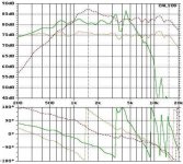
I pulled up my impedance measure of the B110 and there is no resonance anywhere near the 1 kHz notch in their low pass filter (see below, freq, mag, phase). The impedance is fairly benign there. Driver impedance loading will not fill in this dip on the low pass.
I also pulled out my B110 measurement (in JR149, attached) and there are no unusual break up modes or peaks near the filters 1 kHz low pass notch.
The 1 kHz low pass notch has nothing to do with electrical loading.
I'm now certain in my comment as it applies to the woofer, and it makes sense when thinking about what KEF were trying to accomplish. KEF were attempting to achieve butterworth response in the acoustic domain and in order to do so, they had to provide shaping that equalizes out the diffraction. Had to. I have the old KEF acoustic butterworth papers and they were being very specific to try and hit this target with very tight tolerances, and at one observation point in space.
That cabinet size puts the diffraction peak right at where that low pass notch was. the notch may also be equalizing out artefacts of the driver being mounted behind the baffle.
The diffraction signature varies with observation point so the "acoustic butterworth" can only be achieved at one location in space. In my experience as supported in 2 years of measuring and tuning the modded JR149 and many many years doing the same with other speakers, this approach (flat at one observation point above all else) creates tonal error in the in-room response and at off axis positions. But it depends upon the room and where the speaker is placed (ie how strong the early reflections are). You might get away with it in a very large room with the speaker away from boundaries, but that's not what these were meant for.
B110 impedance:
850.7931, 9.455524, 19.59092
854.4922, 9.455343, 19.69333
858.1913, 9.467574, 19.65625
861.8904, 9.45946, 19.75795
865.5895, 9.443473, 19.84098
869.2886, 9.449256, 19.81716
872.9877, 9.449752, 20.04765
876.6868, 9.449234, 20.04595
880.3859, 9.478506, 20.19978
884.085, 9.478559, 20.3033
887.7841, 9.480725, 20.39425
891.4832, 9.491385, 20.43211
895.1823, 9.475617, 20.44438
898.8814, 9.457897, 20.60083
902.5805, 9.485962, 20.79664
906.2796, 9.490391, 20.82899
909.9787, 9.496973, 20.93588
913.6778, 9.482034, 20.96888
917.3769, 9.501637, 21.20304
921.076, 9.509802, 21.48127
924.7751, 9.515588, 21.39674
928.4742, 9.530795, 21.66863
932.1733, 9.567492, 21.75328
935.8724, 9.574621, 21.77176
939.5715, 9.580082, 22.01567
943.2706, 9.598657, 22.03609
946.9697, 9.61547, 21.93688
950.6688, 9.643554, 22.0292
954.3679, 9.630728, 22.19983
958.067, 9.646572, 22.40276
961.7661, 9.63136, 22.36178
965.4652, 9.661106, 22.46208
969.1643, 9.668074, 22.51344
972.8634, 9.680964, 22.72657
976.5625, 9.667365, 22.84811
980.2616, 9.7003, 22.90899
983.9607, 9.706642, 22.98372
987.6598, 9.745298, 23.11203
991.3589, 9.750814, 23.2664
995.058, 9.748116, 23.25147
998.7571, 9.792521, 23.40606
1002.456, 9.785412, 23.44017
1006.155, 9.796238, 23.5227
1009.854, 9.808895, 23.40072
1013.553, 9.820336, 23.51541
1017.253, 9.821096, 23.686
1020.952, 9.857427, 23.77289
1024.651, 9.861971, 23.878
1028.35, 9.869364, 23.88871
1032.049, 9.879936, 23.88483
1035.748, 9.889774, 24.1453
1039.447, 9.900518, 24.31965
1043.146, 9.917247, 24.34113
1046.845, 9.961581, 24.42026
1050.544, 9.963982, 24.4767
1054.244, 9.985685, 24.46133
1057.943, 9.994103, 24.66278
1061.642, 10.00965, 24.71018
1065.341, 10.01712, 24.62895
1069.04, 10.02907, 24.75147
1072.739, 10.03414, 24.90763
1076.438, 10.01787, 24.97557
1080.137, 10.06508, 25.11204
1083.836, 10.09658, 25.24223
1087.536, 10.12495, 25.45451
1091.235, 10.11917, 25.26255
1094.934, 10.13633, 25.30299
1098.633, 10.14205, 25.40691
1102.332, 10.16461, 25.55765
1106.031, 10.15422, 25.58936
1109.73, 10.18866, 25.86483
1113.429, 10.21197, 25.89085
1117.128, 10.23635, 26.01495
1120.827, 10.24725, 25.96425
1124.527, 10.26749, 26.21195
1128.226, 10.30055, 26.23612
1131.925, 10.3165, 26.2911
1135.624, 10.32664, 26.27637
1139.323, 10.37328, 26.38197
1143.022, 10.36664, 26.43386
1146.721, 10.38662, 26.47898
1150.42, 10.40094, 26.51083
1154.119, 10.41923, 26.5971
1157.818, 10.43409, 26.78909
1161.518, 10.47815, 26.76176
1165.217, 10.49545, 26.81145
1168.916, 10.50115, 26.84913
1172.615, 10.53347, 27.01813
1176.314, 10.56664, 27.02847
1180.013, 10.58233, 27.00371
1183.712, 10.61933, 27.12609
1187.411, 10.64628, 27.06968
1191.11, 10.66716, 27.1574
1194.809, 10.67169, 27.17775
1198.509, 10.69459, 27.09879
1202.208, 10.74225, 27.13801
1205.907, 10.76876, 27.20633
1209.606, 10.78171, 27.25706
1213.305, 10.8055, 27.35069
1217.004, 10.82825, 27.33644
1220.703, 10.84982, 27.39726
1224.402, 10.84948, 27.30831
1228.101, 10.9001, 27.32062
1231.8, 10.91935, 27.3416
1235.5, 10.94889, 27.4024
1239.199, 10.98443, 27.27279
1242.898, 11.02042, 27.22119
1246.597, 11.0504, 27.32913
1250.296, 11.06623, 27.28513
1253.995, 11.09727, 27.21359
1257.694, 11.09644, 27.18398
1261.393, 11.11691, 26.93014
1265.092, 11.13916, 27.01236
1268.791, 11.1465, 26.98767
1272.491, 11.15741, 26.9203
1276.19, 11.17753, 26.91002
1279.889, 11.20397, 26.72499
1283.588, 11.20996, 26.65949
1287.287, 11.21928, 26.63239
1290.986, 11.23363, 26.47692
1294.685, 11.22112, 26.4991
1298.384, 11.2471, 26.39837
1302.083, 11.26625, 26.4396
1305.782, 11.23563, 26.29197
1309.482, 11.24623, 26.18811
1313.181, 11.22611, 26.24024
1316.88, 11.23855, 26.16928
1320.579, 11.24086, 26.31536
1324.278, 11.24005, 26.24444
1327.977, 11.22086, 26.31276
1331.676, 11.26161, 26.24234
1335.375, 11.25144, 26.27654
1339.074, 11.27033, 26.17113
1342.773, 11.25619, 26.16072
1346.473, 11.2405, 26.19431
1350.172, 11.24936, 26.35818
1353.871, 11.22452, 26.32448
1357.57, 11.22958, 26.33811
1361.269, 11.23894, 26.39795
1364.968, 11.25263, 26.40335
1368.667, 11.25736, 26.36006
1372.366, 11.23291, 26.47322
1376.065, 11.25498, 26.43444
1379.764, 11.25536, 26.49589
1383.464, 11.24352, 26.62811
1387.163, 11.26574, 26.63741
1390.862, 11.25267, 26.70881
1394.561, 11.2934, 26.80534
1398.26, 11.26629, 26.74272
1401.959, 11.29433, 26.85488
1405.658, 11.31246, 26.80833
1409.357, 11.34068, 26.87562
1413.056, 11.32965, 26.80629
1416.755, 11.3199, 26.9342
1420.455, 11.33812, 26.94658
1424.154, 11.35117, 27.04415
1427.853, 11.37551, 27.0208
1431.552, 11.35686, 27.02983
1435.251, 11.36028, 27.08681
1438.95, 11.39218, 27.06027
1442.649, 11.39287, 27.203
1446.348, 11.38505, 27.18962
1450.047, 11.38108, 27.23181
1453.746, 11.42091, 27.21808
1457.446, 11.44403, 27.25867
1461.145, 11.42723, 27.1525
1464.844, 11.46145, 27.17983
1468.543, 11.44504, 27.28015
1472.242, 11.45559, 27.23314
1475.941, 11.45078, 27.22016
1479.64, 11.46242, 27.24592
1483.339, 11.48027, 27.26957
1487.038, 11.478, 27.27693
1490.737, 11.4808, 27.28284
1494.437, 11.48308, 27.44191
1498.136, 11.5113, 27.37543
1501.835, 11.48783, 27.55301
1505.534, 11.49328, 27.56037
1509.233, 11.49688, 27.58562
1512.932, 11.51933, 27.55192
1516.631, 11.53422, 27.66614
1520.33, 11.54593, 27.61449
1524.029, 11.54227, 27.68884
1527.728, 11.56985, 27.6107
1531.428, 11.55655, 27.61876
1535.127, 11.54488, 27.61539
1538.826, 11.56679, 27.70486
1542.525, 11.56386, 27.83685
1546.224, 11.59855, 27.95904
1549.923, 11.62116, 27.90408
1553.622, 11.61546, 27.97515
1557.321, 11.62303, 27.85656
1561.02, 11.62471, 27.90169
1564.719, 11.63849, 27.79343
1568.419, 11.63289, 27.78188
1572.118, 11.64816, 27.93269
1575.817, 11.65404, 27.94246
1579.516, 11.63076, 27.90508
1583.215, 11.64012, 27.84087
1586.914, 11.6469, 27.88881
1590.613, 11.65741, 28.0315
1594.312, 11.66255, 27.95726
1598.011, 11.66602, 28.08627
1601.71, 11.65934, 27.98147
Tweeter:
Attachments
Last edited:
Dave you know from probably 20 years ago that I get the diffraction thing. Diffraction bumps are not usually as high Q as the notch that is in that crossover but I'm going to try and not get into a back and forth yet again with you. I believe that certain revisions of the B110 had a resonance that was "corrected" in this crossover. So, if the OP plans to use the same spec drivers as in the KEF CS1A design, in a baffle with similar dimensions, and with it front mounted this crossover might be a good choice. This is all that I was suggesting by posting the links in the first place.
Having dealt with you in the past I do think that you are deliberately contrarian Dave, as you are quick to point out who is right in your mind. I was not suggesting to use this crossover with a JR149 type box. I said previously that the woofer would not have an impedance peak at the notch frequency - that should be obvious.
You wrote:
"If I come up with an alternative view, its for technical reasons only. I'm not trying to be contrarian, its no fun having learned people ignore the facts I present because they don't follow an orthodoxy or reputational pecking order."
The "facts I (you) present" are you sure they are facts? Do you have in spec B110 SPL measurements directly driven in the KEF CS1A enclosure and measurements on a large flat baffle to prove that it is diffraction?
You wrote:
"The T27 had a resonance of 1200Hz, so that explains the notch in the high pass to 8 ohms."
So if you knew that the T27 had a resonance of 1200 Hz then why were you so quick to leap to
the conclusion that I was wrong and that it was diffraction - to be a contrarian.
I find this really annoying and I remember this pattern from past discussions with you.
Last edited:
Pete, I thought the t27 fs was much higher. I looked it up after I posted (it wasn't easy to find) and at that time realized I was incorrect about the high pass notch. I stand by the rest.
Regarding diffraction,yes, I have a model of that baffle size and the peak is at 1 kHz.
I post what I think is technically correct and back it up. I'm sorry you take it personally.
Regarding diffraction,yes, I have a model of that baffle size and the peak is at 1 kHz.
I post what I think is technically correct and back it up. I'm sorry you take it personally.
I did it this way, Pete. So I found out, that this gifs were the same I used some years ago to build my CS1a and I published at Post #172Seems that you have to go though the main page to get to those .gifs:
Yes, the CS1a has a volume of about 7.6 L and the outer dimansions are a bit bigger.I believe that the CS1A is a third greater in volume than the LS3/5a (8L -v- 6L). I'm not sure about the Falcon Acoustics Mini Monitor but I believe that it too is larger than the LS3/5a?
But KEF declared it as a deriv of the LS3/5A:
Further informations you will find here: Constructor Series CS1 to CS9Constructor Series Model CS1A (1981-90)
The CS1A was a bookshelf two-way system based on the BBC LS3/5A.
I was trying to point out two broad factors that need to be considered, but that weren't:
- one pass/fail criteria ala Harwood can't be applied without factoring in q of the resonance or more recent and complete research on the topic of audibility. Adding stiffness increases q, so even though the level is higher, it may not be more audible. Secondly, Harwood was too lenient in allowing resonances at lower frequencies
- I pointed out the beneficial effects of bracing, internal absorption and driver decoupling to a heavy stiff cabinet with high resonance points and myself and others pointed towards useful data in this regards
I agree it would be nice to see measured data detailing pros/cons beyond the Harwood paper but I raised enough skepticism that its woefully incomplete and out of date.
Adding stiffness doesn't typically increase Q. Of course there are a number of possible scenarios, but the most typical one discussed in the forums is of assuming a material and then considering what thickness is best. The vast majority of cabinets are MDF or (a distant second) plywood. Both Barlow and Harwood show measurements of the specific case of varying wall thickness of a cabinet or barrier. For both, resonances go up in frequency but do not change in Q. Specifically, the panel output (Harwood uses a microphone nearfield to the center of the cabinet surfaces) at the resonant peaks is constant.
I have no argument with the Olive data on audibility of resonances. It is good to expand our understanding of the topic. I would repeat my caution on its interpretation, especially when applied to mechanical systems. Adding damping to reduce resonance Q is always desrable because the peak level drops at twice the rate that the perceptability increases. This needs to be understood.
I would assume that there was common ground between the Harwood numbers and the Olive numbers. It is worth discussing Harwood's method. He simply sampled a large number of cabinets and noted the frequency and level of the significant panel resonances (vs. Mean woofer level) and also whether they were audible or not.
From this he could plot a nominal boundary between audible and non-audible. This is a very practical approach. We have to be careful not to generalize too far beyond his specific cases (mid sized 2 and 3 way loudspeaker cabinets) but for that his methodology is sound. I don't accept any arguement that it is out of date. Cabinets are still made out of wood and our hearing mechanism, to my knowledge, has not eveolved. As to Harwood's rise in the threshold at low frequencies, I would guess that was tied to his approach of taking nearfield panel measurements.
As to bracing or driver decoupling, They are valid approaches. Andrew's paper backs up what was previously found at KEF (where we both worked): cabinet vibration is largely driven by direct acceleration from the woofer chassis.
For the majority of diy builders who don't go down the path of decoupling, effective damping is the best course and excessive cabinet mass or rigidity makes that difficult.
David S*
activating a panel vibration
When a panel is shaken transverse to it's width/length, it vibrates. Sometimes at it's resonant frequency or harmonics thereof. Imagine Rolf with his metal board making music.
What if the panel is vibrated along the line of the panel, such that there is no transverse activation?
Does the panel start to resonate?
Applying the answers from the above:
does the front panel mounted speaker "shaking" the front panel make all other panels of the boxed speaker resonate, or do the side panels remain benign and only the front and back panels resonate?
- Status
- This old topic is closed. If you want to reopen this topic, contact a moderator using the "Report Post" button.
- Home
- Loudspeakers
- Multi-Way
- Can one build a better (non) LS3/5A speaker based on T27s & B110s?