Hello Mile,
I'm an new hobbiest, and started an subwoofer amplifier which is simple and choosen making D14 from post #31 Sch and Post#34 Wiring Daig and PCB. (Selecting this amp cause its an autobais)
My PCB is ready for further. Here i have some queries as follows.
1. C4, C12, C11 polarity is reverse - Schematic or PCB-Post #34.
2. R3 - 1K Missing from part list. Plz correct me.
3. R18, R19 - 82R instead of 220R - is it ok.
4. R17 - 330R instead of 220R.
5. May you suggest any PSU and Protect for this amp.
Thx & Rgds, Anjan
Hi Mr.Miles..
I'm so interest about kelvin amp.but any problem for me about some part like the transistor
in my place is so hard to find it.I need your suggesting..can I replace MJE340/MJE350 with BD139/BD140 and BDW83D/BDW84D with 2SC5200/2SA1943? thank
Best Regard
With +/-40V dc rail you can use BD139/140 instead MJE340/350 and TIP142/147 or similar darlington transistors, 2SA1943/2SC5200 can't be use it's not darlingtons.
Hi..Mr.Miles
How about 2N3055/MJ2955 can use instead BDW83D/BDW84D.thanks
Regard
No, only darlingtons can be used, if you have promlem to find it I suggest AX11...
Ok ..Mr.Miles thanks for your suggest,sorry to much question.I will built AX11 but I can't to find MPSA13 in my local market,the others part for AX11 has been ready,what a kind of type for replacement MPSA13?
I think MPSA series is rarely to sell in my place.thanks
Regard
I think MPSA series is rarely to sell in my place.thanks
Regard
Use BC517 with reverted pins,Ok ..Mr.Miles thanks for your suggest,sorry to much question.I will built AX11 but I can't to find MPSA13 in my local market,the others part for AX11 has been ready,what a kind of type for replacement MPSA13?
I think MPSA series is rarely to sell in my place.thanks
Regard
Regards
Hi Mr Mile!Use BC517 with reverted pins,
Regards
Instead MPSA13 (APX-11) can be used BD679 for better editing.
")
Mile may need to add a trimmer on the bias schematic for the BD679.
Миле можда треба додати неки тример на шеми за биас са BD679?
Thanks for your help!
Hi Mr Mile!
Instead MPSA13 (APX-11) can be used BD679 for better editing.
Mile may need to add a trimmer on the bias schematic for the BD679.
Миле можда треба додати неки тример на шеми за биас са BD679?
Thanks for your help!
Yes you can upgrade circuit with BD679 and trimmer.
Regards
What bias current do you use?
I tend to run mosfet amps with very low bias.
I have seen crossover distortion go wit has little as 10mA.
Peavey are a great fan of low bias currents too.
After all anything more than enough to get rid of crossover distortion is just wasted in heat.
Hi..Mr.Miles
I was tried build the kelvin amp and I follow your advice for the part where I can substitute.MJE340/350 instead BD139/140,MPSA13 instead BC517 and the final trans.I use TIP142/147,and the result have a problem.the out put current is 6 volt more and sound come hum.what is a wrong there? I made PCB with transfer toner and I was checked for the polarity
is correctly.thank for the answer
Hi..Mr.Miles
I was tried build the kelvin amp and I follow your advice for the part where I can substitute.MJE340/350 instead BD139/140,MPSA13 instead BC517 and the final trans.I use TIP142/147,and the result have a problem.the out put current is 6 volt more and sound come hum.what is a wrong there? I made PCB with transfer toner and I was checked for the polarity
is correctly.thank for the answer
Post pictures and don't forget to connect input gnd to psu gnd with separate wire.
I was build like this,and I put the gnd from psu directly for input and output.I tested with 12V,than I checked the output current come 6,13 volt dc.please tell me if any mistake with this picture.
one more I have finished build AX11,when I test with 12v it is no problem,and sound is good enough I checked dc current from the output is come 0,03mv.but when I connected with 30v,one resistor with value 47R is burning.I used 47R / 1/2 W.Should I use up 1watt?the resistor is burning from positive rail.thank for all.
Best Regard
An externally hosted image should be here but it was not working when we last tested it.
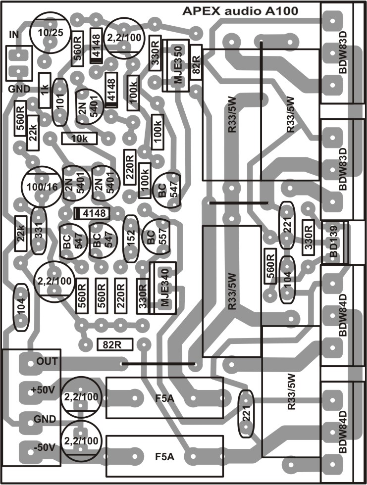
D14 Subamp
Thank you Mile and all DIY contributors,
Successfully made D14 amp for my 10" Peerless subwoofer .(+/- 42v DC)


Sound is fantastic. F100 is on the way.
Need Advice from Mr. Mile.
For Hifi Home listening what do you advice, AX14 / B80 /AX11.
Not concern abt power but good sonic.
Regards
AD
For all aplication especialy for subwoofer I recomend you Kelvin amplifier without VI limiter. You also need active X-over for subwoofer.
Thank you Mile and all DIY contributors,
Successfully made D14 amp for my 10" Peerless subwoofer .(+/- 42v DC)
Sound is fantastic. F100 is on the way.
Need Advice from Mr. Mile.
For Hifi Home listening what do you advice, AX14 / B80 /AX11.
Not concern abt power but good sonic.
Regards
AD
Ask for schematic difference
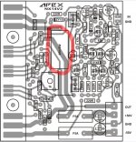
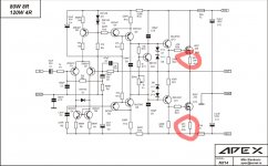
Mr. Mile, in your schematic use final NPN transistor only, how to change for use PNP only, i have a lot off PNP trans with no pair.
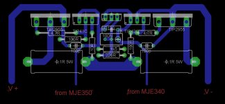
second, why in your schematic use 2pc 5w resistor, but in pcb use one only???
Mr. Mile, in your schematic use final NPN transistor only, how to change for use PNP only, i have a lot off PNP trans with no pair.
second, why in your schematic use 2pc 5w resistor, but in pcb use one only???
Attachments
Mr. Mile, in your schematic use final NPN transistor only, how to change for use PNP only, i have a lot off PNP trans with no pair.
second, why in your schematic use 2pc 5w resistor, but in pcb use one only???
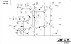
Quasi PNP
Attachments
- Home
- Amplifiers
- Solid State
- 150W MOSFET Amplifier with IRFP250x2