Did somebody tried, using a trasfo with two isolated secondary coils, to regulate/stabilize/filter the both + and -V ground side on a power amp ?
Thats exactly what I did - see my preamp write up for circuit and details.
A Zener is always rated at a voltage below 6.2V. The higher voltage devices work on a different principle and are usually VERY noisy.
. . . not as noisey as an LM317 without the reference decoupled which is ~15uV/V of output voltage. Avalanche diodes are better than this - this is my point.
See Christer's measurements here:-
http://www.diyaudio.com/forums/parts/35821-some-noise-measurements-leds-zener-diodes.html
Note that some of the 12V diodes are actually very quiet - but one of them is quite noisy at 25uV. I suspect the quiet ones may be two low voltage devices stacked.
However, an LM317 with undecoupled Adj pin is about 300uV of wideband noise for the same output voltage.
If you go the whole hog, you can get the 317 noise down to about 20uV wideband at 15V output. Add a decent cap x and you are at 1uV in the mid band.
Last edited:
Thank you for the circuits Mr. Curl, keantoken and dadod.
At least you noticed my PS regulator, nobody else did.
I don't see way to use capacitance multiplier for a preamplifier where no need for high current, when a shunt regulator is much better.
Dejan, do you mean that it's Zout is too large with respect what you would want?
Jan
Actually, I don't see zeners as a problem, even the basic selection is rich enough for just about any taste, and if one wants something really exotic, one can always put two in series.
I was raferring to the available current before odd things start happening. IN my experience, people temd top overlook working out exactly how much current will and pssibly may be required, and tend to use less of a trannie than they should. Some also forget that say 60 mA at say 62V is actually 3.6W and at that dissipation, almost any trannie will need some decent heat sinking. I usually see some weedy little things, as if the trannie's performance is guaranteed by law irrespective of heat.
Usually, I get MJE 15030/15032 to do the job, and use a decent heat sink with thermal coupling.
Well you referred to a specific reg issue and that was my question about, but now you switch to undersized xformer etc. Still in the dark what your point was exactly, but that's OK. Not life-critical.
Jan
Ahhhh ... lower audible distortion!! Who would have thunk it, making a system work better - that's dangerous thinkin', right there, Dejan ...")
I prefer to say less current starvation of the output stage. It seems logical to me that if the output stage needs a certain amount of current and does not get it, it will start to struggle, which will show up distortion sooner or later. You have to let 'em breathe, Frank.
On the message prior to this one - I do not think distortion is of no consequence, quite to the contrary. However, I do believe that its overall value is less important than its shape, so to speak. In other words, I feel that a good harmonic decay rate, with a logical progression, is far more important than whether the absolute peak value is 0.1 or 0.01%.
Well you referred to a specific reg issue and that was my question about, but now you switch to undersized xformer etc. Still in the dark what your point was exactly, but that's OK. Not life-critical.
Jan
Then I obviously did not understand your question. A fair question demands a fair answer.
I suggest we leave that for later on today, after I have posted the regs I use, schematics usually simplify things.
Bonsai, did-you compared in the two senses of the AC plug the voltage between the ground and some earth (or another device connected to the earth) between traditional PSU and this config ?Thats exactly what I did - see my preamp write up for circuit and details.
Did-it gaves an obvious improvement ?
John Curl, as you use both regulation and cap multiplier, it should be a good idea to set the regulation ground sides, like in my last schematic, followed by your cap multiplier on the rails sides ?
AC isolation is the goal.
Last edited:
A Zener is always rated at a voltage below 6.2V. The higher voltage devices work on a different principle and are usually VERY noisy.
~6V zeners have about zero tempco, nothing to do with noise. Some low voltage zeners are built in a special process, to avoid the surface breakdown, which is usually the main noise contributor. These are called "buried zeners" and a typical example is LM329.
But, by whatever criteria, zeners (of whatever voltage) are very noisy, period.
Then I obviously did not understand your question. A fair question demands a fair answer.
I suggest we leave that for later on today, after I have posted the regs I use, schematics usually simplify things.
#58120. I thought the question wasn't that hard.
jan
I mainly used this approach to keep PSU filter cap charging currents and noise completely out of the clean DC side. I have not checked to see if there is any benefit on AC plug orientation.
You can of course wire the secondaries in anti phase to get partial cancellation of the leakage flux associated with charging currents, but as I remarked elsewhere, this really works well when the secondaries are bifilar.
You can of course wire the secondaries in anti phase to get partial cancellation of the leakage flux associated with charging currents, but as I remarked elsewhere, this really works well when the secondaries are bifilar.
Anyway, here's the small shunt I use, and yes, there is a bigger one, much better but also much more complicated and far more costly.
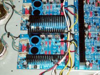
One are its schematics with a Vout table, second picture is a detail of it in real life and the third is how two of them actually look inside the case, for a true dual mono. Not seen but present nevertheless are two custom toroidal transferomers, rated at 50 VA each. All that for a headphone amplifier, also usable as a preamp, if you're happy with just two sources.
One are its schematics with a Vout table, second picture is a detail of it in real life and the third is how two of them actually look inside the case, for a true dual mono. Not seen but present nevertheless are two custom toroidal transferomers, rated at 50 VA each. All that for a headphone amplifier, also usable as a preamp, if you're happy with just two sources.
Attachments

Here's what I use as a stabilizer for power amp input, VAS and predriver stages. Not the most sophisticated you ever saw, to be sure, but in my view one of the best sounding.
It is scaleable, however bear in mind that the more current you want from it, the bigger the local star shaped heat sink will need to be. After 60 minutes of normal operation in a 25 deg C ambient the heat sink should not exceed 10 deg C more.
It is scaleable, however bear in mind that the more current you want from it, the bigger the local star shaped heat sink will need to be. After 60 minutes of normal operation in a 25 deg C ambient the heat sink should not exceed 10 deg C more.
Attachments
The textbook regulator. Jan will probably be happy to note a classic NFB loop, he likes these things.
I don't remember where I got the basic schematic from, it was a long, long time ago, in another galaxy, far, far away ... Anyway, I made it a couple of times, and on two occasions actually scaled it up for the whole power amp, but was not very happy with the results. More detailed was revealed, but the speed became a problem. I thought I might try some MOSFETs, but never actually did.
I don't remember where I got the basic schematic from, it was a long, long time ago, in another galaxy, far, far away ... Anyway, I made it a couple of times, and on two occasions actually scaled it up for the whole power amp, but was not very happy with the results. More detailed was revealed, but the speed became a problem. I thought I might try some MOSFETs, but never actually did.
Attachments
AC plug orientation changes capacitive leakage currents, for class II instrument.
Here in Taiwan, the plug and socket only allow insertion one way on more modern equipment - same in Japan I noticed as well.
Modern SMPS designs feature x-cap discharge circuits for the reason you stated as well.
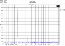
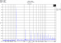
Few weeks ago, we discussed opamp loading and shown some examples of good behavior. Today, it happened to me to measure a conventional headphone output with NJM4565 opamp. 90% of consumer electronics would have it inside. Please see measurement without load and with 50 ohm load, at only 1V peak-peak (0.35Vrms). With 50 ohms, you may see purely crossover distortion - and it sounds exactly this way - sterile, aggressive, gray, harsh sound. I often wonder what the guys who make listening tests directly from PCs with headphones will hear.
Attachments
You are free to modify a strip outlets.Here in Taiwan, the plug and socket only allow insertion one way on more modern equipment - same in Japan I noticed as well.
DIY rocks ;-)
- Status
- Not open for further replies.
- Home
- Member Areas
- The Lounge
- John Curl's Blowtorch preamplifier part II