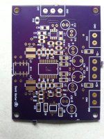
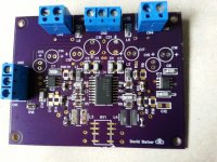
IC1a is half wave rectifier, IC1b is integrator, T2 is variable resistor and T1 is start-up network
What's being discussed here?
Roll Your Own?
So for relatively low value resistors...
Is it better to use Ferrite beads or roll your own?
This would be the roll your own for the latter.
But wondering, someone probably makes a SMD resistor network that
can be programmed or set using dip switch?
Any one of a good brand for this? I guess from reading you'd want
some type of miniMELF configuration?
So for relatively low value resistors...
Is it better to use Ferrite beads or roll your own?
Are surface mount thin film and metal film resistors equivalent to the through hole parts in linearity? You can cram a lot more in a given space for even less money. I suspect a network with some compensation for frequency can be built using surface mount resistors on both sides of a PCB. Using quality metal film resistors in networks to reduce the individual stresses looks to be a good solution, unless you need really high precision. Then you need something better.
This would be the roll your own for the latter.
But wondering, someone probably makes a SMD resistor network that
can be programmed or set using dip switch?
Any one of a good brand for this? I guess from reading you'd want
some type of miniMELF configuration?
I did find this : http://www.ece.unm.edu/summa/notes/ESDN/ESDN 2.pdf which discusses wirewound resistors with uniform resistance to several MegaHertz. And this which is a bit of history for resistor fanatics : http://www.nist.gov/calibrations/upload/rp1323.pdf from 1940. We have not moved a lot further, with the exception of Josephson Junctions which are not useful for anything but calibration.
yes, i remember.... I was there.... bought the B&K1607, got a mod for it done and used it to determine how good the QA400 would be... after finding the QA400 became nonlinear below -100dB. Improved it by at least 20dB.
It is nice to work with people with a lot of talent to push things even further without spending a small fortune. Well.... actually I have spent a small fortune... but maybe other's wont have to.
THx-RNMarsh
I've been looking around for it but perhaps I missed it.
To improve the QA400 another 20 dB What do I need to mod on it?
I'm going back through everything while I wait on the last parts
before digging into some of my test gear...Namely HP339A.
I'll be putting into practice the research and development work performed by Davada, Demian, Richard, Richiem, and other's who've contributed their
time and efforts.
FYI - The small fortune spending (Ssf) is relative to the following:
Glow - How low do you want to go, add 1 for each (.0) place: (i.e., .1 = 1, .01 = 2, ... n = places).
Ssf = [(income - expenses) + desire to succeed] ^ 3 + Glow
Thank you gentlemen for saving me $$$$$$$
Had to put the parenthesis around the exponent (3 + Glow)FYI - The small fortune spending (Ssf) is relative to the following:
Glow - How low do you want to go, add 1 for each (.0) place: (i.e., .1 = 1, .01 = 2, ... n = places).
Ssf = [(income - expenses) + desire to succeed] ^ (3 + Glow)
Thank you gentlemen for saving me $$$$$$$
Last edited:
I've been looking around for it but perhaps I missed it.
To improve the QA400 another 20 dB What do I need to mod on it?
Thank you gentlemen for saving me $$$$$$$
You need a notch filter on the front of the QA400 ... same for other adc/sound-card that would be used.
-RM
You need a notch filter on the front of the QA400 ... same for other adc/sound-card that would be used.
-RM
Ok. For some reason I thought you guys tweaked some
of the parts in the QA400 to make is better.
Yep, have two, actually three....B&K 1607, Home Made,
and isn't there a Notch in the HP339A?
To use it w/o meter distrotion, I have to rewire it, from the auto null to
the AM Detector BNC.
Hi Victor,
I have been using your oscillator I bought on Ebay to test modifications I am making to my Boonton 1121 residual distortion. Looks pretty good so far. I am getting < 0.00050% displayed which is much better than a stock Boonton and your oscillator shows slightly lower THD+N than my Tektronix SG 505. Thanks for your help!
Mike
David --- jcx over on the John Curl forum recommended a buffer for your oscillator's OPS -- see #56684. It is a TI part number TPA 6120.
It is a dual device which you can use both in parallel.
THx-RNMarsh
That was the first one tried Richard. If you go back a few months of posts.
I think it was this thread. Covered quite thoroughly. JCX posted this on his own comp amp thread.
You have reports from that.
Last edited:
I am far away and not closely thinking about this in the evening here--- sorry for that. I am soliciting the best help from the best people to help you. I too cannot stand the idea of your hard won efforts would be compromised by the OPS buffer/amp. Let's hope some more ideas for you to try are forth coming soon.
THx-RNMarsh
THx-RNMarsh
Last edited:
I am far away and not closely thinking about this in the evening here--- sorry for that. I am soliciting the best help from the best people to help you. I too cannot stand the idea of your hard won efforts would be compromised by the OPS buffer/amp. Let's hope some more ideas for you to try are forth coming soon.
THx-RNMarsh
Here's what I've found. These IC solutions work great until presented with a load.
A good one will raise the 2nd and 3rd H with a moderate load. As load increase then we get a full spectrum of harmonics. When ever this is seen it the OPS breaking up. That is the only thing that can produce a full spectrum of mostly odd order. Even order junk is just noise or stress on the power supply.
I understand that's it's not possible for and IC manufacture to use class A in an IC. It's been attempted by Japan with the STK package amps but this lead to grief for them as the pack would fail, mostly from lead stress. Just can't handle the heat.
I know this I replaced a ton of them in the 80s 90s.
Looking at the Krohn Hite designs. Anywhere serious output current was needed they used a complementary pair arrangement. Some with feed forward on the current source.
Complementary pair is pure class A.
Finally, no amount of feedback can correct for OPS load distortion at these levels and possibly under any condition. When one thinks about it how can it.
This is an age old problem for push pull OP stages.
I am far away and not closely thinking about this in the evening here--- sorry for that. I am soliciting the best help from the best people to help you. I too cannot stand the idea of your hard won efforts would be compromised by the OPS buffer/amp. Let's hope some more ideas for you to try are forth coming soon.
THx-RNMarsh
Thanks for putting out to the experts.
Everything looks nice in spice.
A BUF634 isn't good enough for you? 250mA into any load....
Hi dirkwright.
It's not a matter of what's good enough for me.
It's what works. So far non of the IC solutions have. Not for this. They all lose it under load.
That's biasing. I haven't found an IC that is biased in class A.
the buffer/CFA DSL drivers have to be used inside another great op amp feedback loop in a multiloop/composite amp to get the sum ppm performance
I like the CFA because they can have local feedback with Vgain so the input op amp isn't working as hard - and can be ran from sub regulated supplies
there aren't single op amp solutions but the composites do have the drive capability - if your layout is up to the demand
multilooped Class AB DSL drivers have the capability with the CFA alone managing -100 dB specs for few hundred mA into 25 Ohm DSL line xmfr primaries
and today's really great ~>~20 MHz input op amps giving 40 dB more distortion reducing loop gain to few hundred kHz
but supply and gnd common impedance coupling of the half wave rectified Class B portions of the load current waveforms alternating in the pos, neg rails require extreme layout care
I have repeatedly shown you can bias paralleled op amp outputs into Class A push-pull - which then should reduce PS, return nonlinear current components, easing layout
I have wrapped all the techniques together - OPA627 input looping paralleled, Class A biased TPA6120, sub regulated input supply
I find It hard to believe you can't get the required performance form such a "buffer" composite even driving few Watts into 50 Ohms - since I have
Finally, no amount of feedback can correct for OPS load distortion at these levels and possibly under any condition. When one thinks about it how can it.
On the surface this is wrong. In the absence of any alien inductive or capacitive coupling the loop-gain reduces the distortion. That is, remove reality from your sims and you get the simulated result which is the purely mathematical one.
In my 40yr. of experience when you talk about the difference between -120dB and -130dB or whatever performance moving a bypass cap an inch or two can matter. The haversine supply currents wreak havoc under heavy load.
I agree with jcx, I have personally run across these issues and it is work to figure them out. If you need two or three layouts of the same circuit so be it.
Last edited:
Hi dirkwright.
It's not a matter of what's good enough for me.
It's what works. So far non of the IC solutions have. Not for this. They all lose it under load.
That's biasing. I haven't found an IC that is biased in class A.
Depends on how much class A load you need. The BUF634 can be set to 30mA quiescent IIRC.
That would be 20mA RMS, or 12VRMS in 600 ohms, class A.
What's your requirement?
Jan
the buffer/CFA DSL drivers have to be used inside another great op amp feedback loop in a multiloop/composite amp to get the sum ppm performance
I like the CFA because they can have local feedback with Vgain so the input op amp isn't working as hard - and can be ran from sub regulated supplies
there aren't single op amp solutions but the composites do have the drive capability - if your layout is up to the demand
multilooped Class AB DSL drivers have the capability with the CFA alone managing -100 dB specs for few hundred mA into 25 Ohm DSL line xmfr primaries
and today's really great ~>~20 MHz input op amps giving 40 dB more distortion reducing loop gain to few hundred kHz
but supply and gnd common impedance coupling of the half wave rectified Class B portions of the load current waveforms alternating in the pos, neg rails require extreme layout care
I have repeatedly shown you can bias paralleled op amp outputs into Class A push-pull - which then should reduce PS, return nonlinear current components, easing layout
I have wrapped all the techniques together - OPA627 input looping paralleled, Class A biased TPA6120, sub regulated input supply
I find It hard to believe you can't get the required performance form such a "buffer" composite even driving few Watts into 50 Ohms - since I have
Okay fare enough.
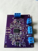
The lay out is a copy of TI's evaluation board with the addition of OPA1611 for the comp.
The design is pretty much what you proposed a few months ago here and on your thread.
The only difference is it's running at a gain of 3 or so and in non inverting configuration.
The board is designed as an development board and can configured for either a non inverting or inverting mode.
The usual supply bypassing power pins to ground is not working. I'm finding better success with rail to rail by passing of the larger electrolytic.
I'll post some pics of the board.
- Home
- Design & Build
- Equipment & Tools
- Low-distortion Audio-range Oscillator