Back to this...
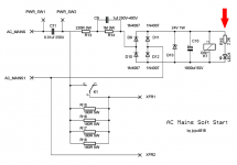
I'm trying to understand what governs the time taken before the power relay trips the bypass of the resistor bank (R3-R6). I have no experience with power relays so some help would be appreciated. The datasheet for the G5LA is "sparse" to say the least. (I presume pins 2 and 5 are for powering the relay, pin 1 is the inbound line being switched, and that the unit switches output from pin 4 to 3 when 'ready'.)
BigE, I didn't take a close look at your LTspice modelling. Did you model the actual behaviour of the G5LA or just use a simple switch with a time delay function?
The normal way to refer to these is pin1 = compin 1 is the inbound line being switched, and that the unit switches output from pin 4 to 3 when 'ready'.)
pin4 = NC
pin3 = NO
Com = common
NC = normally closed
NO = normally open.
Is that confirmed in the datasheet?
The design of this project leaves the "timing" dependant on the capacitor value, on the resistor value, on the mains supply voltage, on the speed of build up of voltage on the diodes+ capacitor.what governs the time taken before the power relay trips the bypass of the resistor bank
The timing needs to be measured on your project, then come back and ask how to change, if it does not suit.
Thanks for the proper nomenclature. There is only a diagramme but it does appear to confirm the above.
It's the action of the relay that I am most inquiring about. (No need to explain D1-D6, C3, R7, R3-6.) Current through R1, R2, C2 slowly magnetising the coil of the G5LA which 'trips' when at a certain point? I'm just trying to understand the interaction of R1, R2, C2 and the 1600R coil resistance better.
It's the action of the relay that I am most inquiring about. (No need to explain D1-D6, C3, R7, R3-6.) Current through R1, R2, C2 slowly magnetising the coil of the G5LA which 'trips' when at a certain point? I'm just trying to understand the interaction of R1, R2, C2 and the 1600R coil resistance better.
Andrew, thanks. For some reason I missed your post #151 when typing #152. I see that C2 and R2 is a voltage slew rate mechanism which, when coupled with the coil resistance, acts as a timer.
For what it's worth, I have modelled the circuit. One can change C2 and R2 and the relay characteristics such as coil resistance and observe the impact on timing of the switch. (Coil resistance is changed in the file "relay.lib".)
Download zip folder here. Please do let me know any issues with the model and whether it matches experience.
I suggest that it gives another degree of freedom (another "knob" for the lab technician to twirl) when you fit an LED rated for 50mA in position "LED1". This allows you to monkey around with the delay-before-relay-pulls-in, by adjusting the value of resistor R19. You can accelerate the pull-in by setting R19 for 3mA of LED current (R19 = 7K5). You can slow down the pull-in by setting R19 for 50mA of LED current (R19 = 430R), and you can experiment with other R19 values in between. A potentiometer would be the obvious piece of equipment to use in the lab.
Here is one suitable LED among many, the Vishay TLCR5800, and {Here is its sales page on UK-Farnell's website}. More than 600 of them are in stock in UK warehouses, ready to ship. £0.18 but they require you to purchase 5.
Of course there are other ways to fiddle with the relay pull-in speed, most notably the capacitance ratio (C10 / C9)*. Since capacitor values in the vicinity of 1000uF are not closely spaced, (certainly not in-stock at the distributors who will sell at qty=1), this is a coarse adjustment at best. Thus I recommend finding a resistor on the PCB which will let you make fine-grained adjustments ... and R19 fits the bill quite admirably.
*Yes, Virginia, this is a charge pump. Or if you prefer, you can call it a flying-capacitor, switch mode power supply. You won't even be wrong.
Link to Wikipedia for any non-New Yorkers in the audience
_
Attachments
Thanks. I need to adjust a couple of things in the model (most notably my poor initial attempt to model the 24V zener) and I will make it easier to change the value of the coil resistance (i.e. from the schematic rather than the library file). I will try to get it done today or tomorrow.
Presumably for those preferring to use NTCs, resistors R3-6 can be replaced by a single NTC ICL. (When I get the chance I will add an example of that to the schematic as well.)
Presumably for those preferring to use NTCs, resistors R3-6 can be replaced by a single NTC ICL. (When I get the chance I will add an example of that to the schematic as well.)
... my poor initial attempt to model the 24V zener ...
Using my Windows7 version of LTSPICE, when I click on the schematic symbol of a diode, a dialog pops up that includes a button "Pick New Diode". This offers a big menu of presupplied .MODELs of discrete semiconductor diodes. I can sort by diode category, by clicking on the header word "type" (black star below). Then presto, all Zener diodes are grouped together, and I immediately see a 24V zener diode .MODEL, presupplied.
If this is not available on the Mac, what a shame.
Attachments
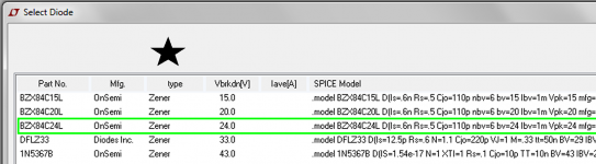
Hmm. Not in my version of LTspice on Windows (at work)... Something wrong with my release. I get an error message when I attempt to sync release as well.
In any event, the learning exercise to roll my own was likely worthwhile. The challenge was relating the spice parameters to the datasheet when they're called completely different things. I still don't know what nbv and Cjo are. The other relevant ones I think I have correct now.
EDIT: synched the release and still don't have it...
Attachments
Last edited:
Back to this...
I'm trying to understand what governs the time taken before the power relay trips the bypass of the resistor bank (R3-R6). I have no experience with power relays so some help would be appreciated. The datasheet for the G5LA is "sparse" to say the least. (I presume pins 2 and 5 are for powering the relay, pin 1 is the inbound line being switched, and that the unit switches output from pin 4 to 3 when 'ready'.)
BigE, I didn't take a close look at your LTspice modelling. Did you model the actual behaviour of the G5LA or just use a simple switch with a time delay function?
I just used a switch, but you can enter the contact resistance. If you are concerned about the coil resistance, that is easy to add as well....
If you are going to "roll your own" I would also suggest a different scheme for applying the mains power..... don't use the keystone screw terminal connectors, as they will leave live power exposed inside the chassis, unless you take special precautions to cover them. In the current design, the mains power goes to the board first, before the switch where it can be connected to a keystone terminal. This terminal will be live irrespective of the position of the switch.
My recommendation would be to delete the keystone connector capability and replace with male spade connector blades all around.
My recommendation would be to delete the keystone connector capability and replace with male spade connector blades all around.
don't use the keystone screw terminal connectors, as they will leave live power exposed inside the chassis, unless you take special precautions to cover them.
Damn... That's a really good point...
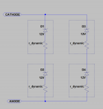
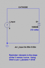
... my poor initial attempt to model the 24V zener ...
Here is one way to do it. This models both the zener knee voltage (24V) and its dynamic resistance (aka slope, aka deltaV/deltaI).
The "r_dynamic" resistances are of course already incorporated into the diode .MODEL equations; I have only drawn them out here for purposes of illustration; you wouldn't include external resistors in a simulation.
If you don't care about correctly modeling the zener dynamic resistance, you can omit D3 and D4.
Attachments
I don't think having all the diode model variables perfectly correct makes any difference to the outcome of this model. So long as BV and IBV are right (both readily available from the data sheet) variances in Is, Cjo, TT, NBV don't change the outcome (time before switch flicks) at least not is ms accuracy. I understand Is is the leakage current but models embedded in LTspice have values for this that are vastly lower than the leakage current numbers listed in the data sheet. I don't believe the other three variables are found in data sheets. Note they are all the same value for any embedded zener model from the On-Semi 1N53 series (5W). Of course, if the variables are explicitly valued the LTspice default values are used.
Last edited:
I would be happy to help you interpret your LTspice results, of simulations which explore this question. Such as the one shown below, which (in my opinion anyway) gives an immediate and completely unambiguous yes-or-no answer on the first try.Mark,
are you saying that the Zener models in LTspice only model the voltage and not the dynamic impedance?
_
Attachments
- Home
- Amplifiers
- Power Supplies
- Soft start circuit design and other psu issues