Hello everyone
I have built a couple of tube phono preamplifier many of them with 12ax7 one of them with 6sn7 but in all of them there are noise, they had good sound amazing midd band but noise makes me unhappy.
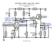
I want to try this one , i beleive it has relativeley little noise because of the mosfet at the output, also some good part of the sound killed by it nevertheless i will try.
In this point i want your suggestioans , if anyone did that phono preamplifier before , please gives me some hint about it. Do i need any tweak ? , actually where i found it , some one talked about that schematic was tweaked before.
Thank you
I have built a couple of tube phono preamplifier many of them with 12ax7 one of them with 6sn7 but in all of them there are noise, they had good sound amazing midd band but noise makes me unhappy.
I want to try this one , i beleive it has relativeley little noise because of the mosfet at the output, also some good part of the sound killed by it nevertheless i will try.
In this point i want your suggestioans , if anyone did that phono preamplifier before , please gives me some hint about it. Do i need any tweak ? , actually where i found it , some one talked about that schematic was tweaked before.
Thank you
Attachments
What kind of noise?Hello everyone
in all of them there are noise,
Hiss? Hum? Buzz? Crackle? Microphonics?
The 12AX7 is a fairly quiet tube and should not give you undue noise (hiss) problems.
Noise normally comes from early stages, not the output stage. The MOSFET is unlikely to improve noise.i believe it has relativeley little noise because of the mosfet at the output,
You have a lot of gain approx. 100+.
That will amplify any noise a lot.
DC heaters should help with hum providing the DC is clean and ripple free.
You have a high output impedance, that could be reduced massively.
Layout is important, short wires/tracks and keep output signals away from input.
Route audio away from any transformers.
Valves should be well away from transformers.
Last edited:
I believe this is Eli's take on the classic RCA circuit, and from what I have heard it works quite well. Should only be a matter of time before he weighs in on this thread.
Build it in a metal box, pay particular attention to grounding. The 12AX7A should be well shielded. This design has relatively poor PSRR so the supply should be really quiet. You might consider Salas' SSHV2 if it is available at the moment.
Build it in a metal box, pay particular attention to grounding. The 12AX7A should be well shielded. This design has relatively poor PSRR so the supply should be really quiet. You might consider Salas' SSHV2 if it is available at the moment.
Hi,
That's really odd. Never noticed any noise from a 12AX7 unless it was faulty.
Are you using a MM cartridge?
Cheers,")
I have built a couple of tube phono preamplifier many of them with 12ax7 one of them with 6sn7 but in all of them there are noise, they had good sound amazing midd band but noise makes me unhappy.
That's really odd. Never noticed any noise from a 12AX7 unless it was faulty.
Are you using a MM cartridge?
Cheers,
As to the 6v heater this looks like it was originally for a 6n2p, not a 12AX7. I agree with others as to noise, quiet PS, quiet heater supply, shouldn't be an issue. and as for massive output impedance, even with the MOSFET? I don't know if the part values for the bias and plate r are suitable for the 12AX7 or if those are also for a 6N2P, but they look close (similar to the RCA phono values).
Hello everyone
I have built a couple of tube phono preamplifier many of them with 12ax7 one of them with 6sn7 but in all of them there are noise, they had good sound amazing midd band but noise makes me unhappy.
The mosfet follower won't affect the noise level at all. The bias on the first tube is too negative. Also, the grid leak bias on the second tube is not good,
use a 1k cathode resistor instead. Are you wiring point-to point? Maybe the layout needs refinement, or a pcb. Metal film resistors will help minimize noise, especially in the first stage. The diagram shows the filaments in parallel by implication. You can elevate them by +40VDC or so with a resistor divider and a decoupling capacitor, taken off the B+ supply. And yes, are you using a typical output magnetic cartridge?
Last edited:
Hi,
The original circuit:

Cheers,
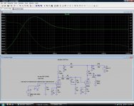
here is an LTspice schematic of the original RCA tube manual circuit
The original circuit:
Cheers,
Here is the correct .asc for the RCA phono stage (forgot to save it with the Laplace expression for the inverse RIAA curve)
How about a PDF?
Huseying,
Few things:
The noise generated by a tube is about inversely related to its gm, which in triodes is again related to Ia. In this respect you are certainly at a quite low gm for an input stage. In fact I would rather use a higher gm tube than ECC83 here at all. My own guess would be ECC88, but there are others with still higher gm. (Also keep in mind we are talking of gm at your operating plate current, which could be quite lower than static specs.) The PSRR will then be poor, but there are other ways of taking care of that.
Then grid leak bias gives lower distortion than cathode bias, but only if fed from a low impedance source, preferably <1K depending. In that sense it is ill-advised here and could add to noise even though it is already a second stage. But most of the noise will come from the input stage, as said.
I fear I fail to see the high output impedance ... A mosfet-follower into 125K? Shouldn't that be in the vicinity of 125K/mosfet gain - or what am I missing here?
(To repeat, one needs to have the input signal voltage you are referring to. It might mean that you have too high gain to begin with.)
Last edited:
The MOSFET buffer makes a world of difference. The RCA original needs to be loaded by 250 K. The O/P impedance with the buffer is under 1 K.
The preferred tube is the clean and quiet Sovtek 12AX7LPS. Buy phono grade stock from a reliable vendor.
"Full wave" voltage double 6.3 VAC with Schottky diodes and regulate with a 7812 3 terminal regulator IC, to obtain the heater supply.
Full wave bridge rectify (low noise diodes please) "230" VAC and filter well. Add an individual LR8 TO92 case high voltage/low current 3 terminal regulator in each channel and B+ is well taken care of.
The tweaked circuit addresses 2 of the 3 shortcomings in the RCA original. Grid leak biasing the 2nd gain block lightly loads the passive EQ network, which improves bass extension. That "trick" was learned from T. Lösch. The MOSFET buffer disposes of the 'X7 triode's inability to drive a load. The issue of high 12AX7 CMiller remains. Some MM level carts. and SUTs behave badly in combination with that "large" capacitance. Most MM carts. and SUTs work just fine.
Attachments
Last edited:
How about a PDF?
Here, try this:
Sorry, I got the schematic wrong initially; I missed the grid resistor on V2.
Could a moderator please remove the previous incorrect schematics?
Attachments
Last edited:
Here, try this:
Thanks, so what causes the low end peaking?
The tweaked circuit addresses 2 of the 3 shortcomings in the RCA original. Grid leak biasing the 2nd gain block lightly loads the passive EQ network, which improves bass extension. That "trick" was learned from T. Lösch.
The coupling capacitor from the first stage certainly causes a lower rolloff frequency due to the high resistance grid leak biasing,
but using a larger coupling capacitor value instead avoids all the grid leak problems.
Last edited:
- Status
- This old topic is closed. If you want to reopen this topic, contact a moderator using the "Report Post" button.
- Home
- Amplifiers
- Tubes / Valves
- RCA Phono Preamplifier with 12ax7