In powder cores you'll have lower amount of magnetic material per volume/cross section thus lower Bs. Losses and coercivity are really high. Low permeability means higher primary turns count. With small signal (like tape recorder heads) it does not matter.
To Jonas. Self inductance of strip 2 cm wide and 100 cm long is around 1 uH.
Driving force in speaker is proportional to current.
Time constant of 0.4 Ohm strip resistance and aforementioned inductance is 2.5e-6 thus 63 kHz -3dB.
In regard to your setup with apparently single turn and frequency > 3 kHz leakage inductance will be 100 times lower... and below 1 kHz probably around 10 times.
If you connect to the secondary wire loop equal to the one in real setup the results will be quite different, again, current wise.
Which was exactly my point why make x-former with no parasitic inductance and then connect wires with "huge" inductance. Simple wire going through the winding window will do the same.
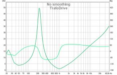
Being not so keen on motor and/mechanics of strip can't really deliberate on the second chart
To Jonas. Self inductance of strip 2 cm wide and 100 cm long is around 1 uH.
Driving force in speaker is proportional to current.
Time constant of 0.4 Ohm strip resistance and aforementioned inductance is 2.5e-6 thus 63 kHz -3dB.
In regard to your setup with apparently single turn and frequency > 3 kHz leakage inductance will be 100 times lower... and below 1 kHz probably around 10 times.
If you connect to the secondary wire loop equal to the one in real setup the results will be quite different, again, current wise.
Which was exactly my point why make x-former with no parasitic inductance and then connect wires with "huge" inductance. Simple wire going through the winding window will do the same.
Being not so keen on motor and/mechanics of strip can't really deliberate on the second chart
Last edited:
On the other hand you can run one driver with ribbon up and another one with down connected in series thus employing return wire for sound production  Not sure if it's proper way of doing it.
On the yet another hand 50 cores stacked with single turn secondary and 5 turns primary is indeed silly and expensive solution.
Since the magnets are of oriental origin the cores of the same origin are cheap as well.
Have fun
Not sure if it's proper way of doing it.On the yet another hand 50 cores stacked with single turn secondary and 5 turns primary is indeed silly and expensive solution.
Since the magnets are of oriental origin the cores of the same origin are cheap as well.
Have fun

I will now try to describe the difference when driving my ribbons with or without transformer.
When I measure phase, distortion or freq response there no difference to talk about.
Then, with transformer, I listen to Bela Fleck "Flight of the Cosmic Hippo" , spotify:track:0dDZPziZGcQV4bUBaKfzyJ (Using Fidelify)
and I hear wonderful music at super Hifi level, I hear how the cymbals are struck with some kind of wooden pin...
Then I switch to without drive transformer, and the difference is that now I also can SEE the cymbals being struck, and with a pin made of Pine...
Last edited:
I have some buckypaper. I could do a resistor with it and compare with the transformer.
High Conductivity MWNT Blend Buckypaper - 12" x 12", 20 gsm
High Conductivity MWNT Blend Buckypaper - 12" x 12", 20 gsm
No, I can't.
Maybe Axelberg can explain?
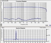
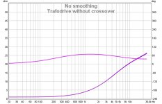
I enclose an impedance graph of trafo driven without crossover and driving a 0.14 ohm resistor. Top curve is phase..
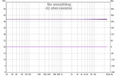
Also a reference graph of a ordinary 42 ohm resistor. Lower curve is phase.
(anybody who knows how to change color for better visual separation of curves in Rew V5?)
Maybe Axelberg can explain?
I enclose an impedance graph of trafo driven without crossover and driving a 0.14 ohm resistor. Top curve is phase..
Also a reference graph of a ordinary 42 ohm resistor. Lower curve is phase.
(anybody who knows how to change color for better visual separation of curves in Rew V5?)
Attachments
Am I right assuming the crossover is present @#151?
the two pics in post151 Claim to show the difference between using the impedance matching transformer and direct drive.Yes!
How come a crossover filter has been added and not declared?
the two pics in post151 Claim to show the difference between using the impedance matching transformer and direct drive.
How come a crossover filter has been added and not declared?
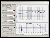
If you read post 151, you can see in the text that the measurements are taken of complete speaker, with bassdriver and then also of course the cross over included...
I just wanted to show the different impedance characteristics of the two drive methods..
So why does the filter not show in the "direct drive" plot?
That's why I asked
That's why I asked
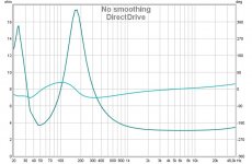
and you came back withCan you explain why the transformer drive version appears capacitive (phase ~60°) all the way from 1kHz to 40kHz?
Whereas the direct drive is substantially resistive (phase +-25°).
No, I can't.
So why does the filter not show in the "direct drive" plot?
You mean in post #151?
- Status
- This old topic is closed. If you want to reopen this topic, contact a moderator using the "Report Post" button.
- Home
- Loudspeakers
- Planars & Exotics
- How to make a good transformer for ribbon tweeter?