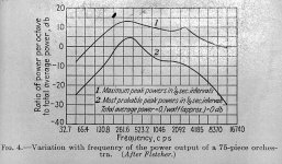
For what it is worth, I can provide the Power Distribution chart. This seems to have been confirmed by a couple other people from other source, one was Bell Labs, and the other was Altec Lansing.

I'm still torn on the Low/Mid crossover. Would it be an advantage to cross at 355hz because that peak load would be shared by two drivers, or would it be better to cross above that peak at 500hz or higher thereby pushing the peak load onto the driver that can most handle it.
Also, isn't a bit of stating the obvious to say you crossover in the 1khz to 4khz range. Isn't that the range where virtually every speaker out there crosses over?
Also, the thread is 85 pages long, so I haven't read everything, but if you are not crossing over in the 1khz to 4khz range, then where are you crossing over?
In a 2-way system, in the 2khz to 3khz range is about the only place you can get Mid-Bass and Tweeters to meet. In a Bass/Mid/High 3-way system, the Low/Mid tends to be between 350hz and 1khz, and that puts the Mid/High in roughly the 3khz to 6khz range.
So to the basic question - Why crossover in the 1-4khz range? I think the only answer can be - where else? Circumstance, mainly the nature and limitation of drivers gives you no other choice.
It seems to me the real question, is - Where is the best/ideal place to crossover? I speak of the theoretical best place to crossover in both 2-way and 3-way designs. If we are not constrained by the limitations of drivers, and we further assume we must still use a 2-way or 3-way systems, where are the hypothetically ideal locations to cross over?
If there are idea locations to cross, it would seem wise for someone to make drivers that conformed with that ideal.
Just a few thoughts.
Steve/bluewizard
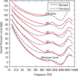
If you look at the revised ISO 226:2003 equal loudness contours and also take into consideration the power distribution of a full 75 piece orchestra crossing over at ~650Hz and ~1.6KHz appear to make some sense in a 3-way speaker. If you want a 2-way system then do what Earl has done. You can go around and around with this stuff, but I've yet to see anything that is a better solution.
Attachments
I don't see how power has anything to do with the problem. That just comes down to the power handling of the drivers at the Max SPL.
The crossover point has to be chosen based on other requirements like polar response matching. Those people who propose 3-ways are completely ignoring the polar response. How do you get CD with a 3-way? It's less that I "want" a 2-way than it is the only feasible option if CD is a design goal.
The crossover point has to be chosen based on other requirements like polar response matching. Those people who propose 3-ways are completely ignoring the polar response. How do you get CD with a 3-way? It's less that I "want" a 2-way than it is the only feasible option if CD is a design goal.
How do you get CD with a 3-way? It's less that I "want" a 2-way than it is the only feasible option if CD is a design goal.
I guess controlled directivity is just one of those things that physics wags it's finger at if you want to avoid crossing over in this region?
I wonder what the polar plots look like on some of the big Genelec monitors...
Edit: Like this one. (attached image)
Attachments
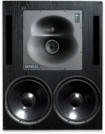
The Genelecs are very good, very expensive and not feasible for DIY. They also have a much wider DI than I would like to see. But they do point out what it takes to get CD in a three way design. And their directivity is not smooth from the woofers to the mid - it goes from tall to wide.
The Genelecs are very good, very expensive and not feasible for DIY. They also have a much wider DI than I would like to see. But they do point out what it takes to get CD in a three way design. And their directivity is not smooth from the woofers to the mid - it goes from tall to wide.
Maybe there's a little DIY possibility with the compound waveguide? I'm sure I could whittle something similar (in the inverse) and fiberglass it...maybe.
Edit: Or maybe as simple as taking two waveguides and trimming a corner off both of them and gluing them together?
Last edited:
The Genelecs are very good, very expensive and not feasible for DIY. They also have a much wider DI than I would like to see. But they do point out what it takes to get CD in a three way design. And their directivity is not smooth from the woofers to the mid - it goes from tall to wide.
That particular Genelec fits your description. The genelec 3-way that most piques my interest however is this:
An externally hosted image should be here but it was not working when we last tested it.
It is so far beyond my DIY Capabilities that I'm just more tempted by it - like a puppy and the other side of the fence.
Last edited:
That particular Genelec fits your description. The genelec 3-way that most piques my interest however is this:
An externally hosted image should be here but it was not working when we last tested it.
It is so far beyond my DIY Capabilities that I'm just more tempted by it - like a puppy and the other side of the fence.
Where'd they hide the third driver, on the back?
Where'd they hide the third driver, on the back?
All three are right there.
All three are right there.
Oh, it's a coax, haha.
But, by no means beyond many DIYer's. I was doing surfboards and airplanes before I could drive! That was 40 years ago! Now we have prepregs, carbon fiber, affordable vacuum pumps, easy to acquire inner laminates like honeycomb and all sorts of bagging materials....Making and using fiberglass molds is not a trivial art.
You do need your imagination connected to your fingers though. Everyone is unfortunately not gifted that way.

But, by no means beyond many DIYer's. I was doing surfboards and airplanes before I could drive! That was 40 years ago! Now we have prepregs, carbon fiber, affordable vacuum pumps, easy to acquire inner laminates like honeycomb and all sorts of bagging materials.
You do need your imagination connected to your fingers though. Everyone is unfortunately not gifted that way.
I gave up working with fiberglass long ago. It was stinky, messy, the molds were hard to make and it was laborious building up something strong. I now cast with odorless polyurethane that setups in just a few minutes, uses molds made of silicone which are easily made, and thickness of several inches is no problem. Downside: Polyurethane is very expensive, but the time savings and hassle reduction are well work it.
Dave Pellegrene uses acrylic plates. He is happy to do custom work.
"creative loudspeaker design that is unequalled in the audio industry" is a bit of a stretch.
I now cast with odorless polyurethane that setups in just a few minutes, uses molds made of silicone...
Like this stuff?
Casting Resins, cast, resin, hobby clear resin, hobby, professional, high quality resins
Originally Posted by weltersys
If crossovers are properly designed for the transducers employed (assuming adequate bandwidth of the transducers), the result is a flat frequency and phase response through the crossover region, the crossover points undetectable either by measurement or hearing (as long as polar response is also consistent), regardless of the crossover frequencies chosen.
Using causal (real time) filters, and physically placing the higher frequency drivers behind lower frequency drivers, it is possible to get a very smooth phase response which can approach flat, but the impulse response will be "smeared", a "downward" phase trend with increasing frequency. Using FIR filters, the phase (and therefore impulse response) can be maintained flat. In either case, the crossover frequency can be undetectable, as long as polar response is also consistent, that "elephant in the living room" often overlooked.
Art
If crossovers are properly designed for the transducers employed (assuming adequate bandwidth of the transducers), the result is a flat frequency and phase response through the crossover region, the crossover points undetectable either by measurement or hearing (as long as polar response is also consistent), regardless of the crossover frequencies chosen.
Earl,Glad you mentioned that little detail of the polar response
Electrical filters are not my expertise, but I was under the assumption all causal filters cause a group delay. So you can get flat response but the impulse response will be smeared. Do you understand differently?
Using causal (real time) filters, and physically placing the higher frequency drivers behind lower frequency drivers, it is possible to get a very smooth phase response which can approach flat, but the impulse response will be "smeared", a "downward" phase trend with increasing frequency. Using FIR filters, the phase (and therefore impulse response) can be maintained flat. In either case, the crossover frequency can be undetectable, as long as polar response is also consistent, that "elephant in the living room" often overlooked.
Art
I would guess that it is the same, but it never does say what it is. Same hardness, same basic price.
but the impulse response will be "smeared"
It shouldn't make any difference how a constant group delay (linear phase) result is achieved wrt impulse response.
Strictly linear phase (phase being a constant multiple of frequency, i.e., "waveform preserving") is not the same as having constant group delay, though. It has to have a phase that can be flattenend to zero degrees (or 180 degrees) by simply adding or subtracting a pure delay.
For instance, if a system had flat 45 degrees phase across a range of frequencies, that system would have constant group delay in that range but will still seriously distort a broadband waveform (such as a square wave) covering that frequency range.
Similarly, having phase that shows as a straight line with constant slope when phase is plotted vs LOG frequency doesn't indicate linear phase either (unless all frequencies are 0 degrees or 180 degrees, a horizontal line). It has to have constant slope on a phase vs. LINEAR frequency plot.
No claims here whether any of this matters or is audible, of course. But the term "linear phase" gets conferred on some speakers that really aren't, even at a single point in space.
- Status
- This old topic is closed. If you want to reopen this topic, contact a moderator using the "Report Post" button.
- Home
- Loudspeakers
- Multi-Way
- Why crossover in the 1-4khz range?