For many years I have avoided making my own boards, preferring the sloppy web of components. Perhaps the time has come to try my hand at creating a printed circuit board.
Can anyone offer suggestions as to how to proceed? Money is, of course, a major consideration so I want to keep my investment small. I only want to make small stuff, say an op amp with a few transistors and passive components.
Alternatively, is there a breadboarding scheme that isn't clumsy and can let me build a few little things?
> is there a breadboarding scheme that isn't clumsy
> and can let me build a few little things?
Pixel Print | Veroboard, Electronic Ready PCB, Stripboard, Perfboard, Components
> and can let me build a few little things?
Pixel Print | Veroboard, Electronic Ready PCB, Stripboard, Perfboard, Components
Thanks for the lightning fast reply! I went to the Veroboard link and frankly I am lost. The parts are there but how to do the job is unclear. What tools do I need, for instance. I am a beginner in this, although my electronics skills are good.
My immediate project, more for experience than a need, uses one opamp (8 pin DIP), one pot, a transistor, and a few resistors. It's intended to control a crystal oven temperature.
My immediate project, more for experience than a need, uses one opamp (8 pin DIP), one pot, a transistor, and a few resistors. It's intended to control a crystal oven temperature.
Easy to find how to use stripboard if you google it. Try : Stripboard
The only special tool needed is a stripboard cutter which is like a drill with a handle so you can make your own.
Even thou I make my own PCBs, I still use stripboard for one off small projects like your oven temp controller.
The only special tool needed is a stripboard cutter which is like a drill with a handle so you can make your own.
Even thou I make my own PCBs, I still use stripboard for one off small projects like your oven temp controller.
Bob, how'd you do?
I'd like to make PC boards for a Sherwood HP-1000 restomod project. It's my first time doing them.
There are three options: send your design to a fab, toner-transfer, or photographic process.
I tried the laser printer toner-transfer method, using glossy advertising circular paper and a wimpy clothes iron. People say you can do this. The results were inconsistent, to put it nicely.
My next step will be to try this process where you print to special-purpose transfer paper, make the transfer using a laminator to apply heat and pressure, and then laminate "laser foil" to the toner to seal it so no etchant can get through gaps in the toner.
Foolishly I'm buying a laminator, even though it cost more ($90) than having the Sherwood boards made in China ($50). I want to do this at home, spin and respin quickly, and have the option of doing more boards in the future.
Thanks for the lightning fast reply! I went to the Veroboard link and frankly I am lost. The parts are there but how to do the job is unclear. What tools do I need, for instance. I am a beginner in this, although my electronics skills are good.
My immediate project, more for experience than a need, uses one opamp (8 pin DIP), one pot, a transistor, and a few resistors. It's intended to control a crystal oven temperature.
Vero board is very expensive, use radio shack proto boards instead.
That stripboard looks interesting. I now have to see where to buy it and whether it's cheap enough for my needs. Thanks for the link!
Solderless plug-in breadboards are great, you can use it for quick experimenting with circuits. It uses #20-22 solid wire for connections.
For actual PCBs, positive photopositive material is incredibly accurate and finish is gorgeous.
How to make your own PCBoards!
How to make your own PCBoards!
The very first boards I did were made from 2oz FR-4 scraps I bought on ebay, some FeCl2 I bought from ratshack, and glossy photo paper prints from my laser printer. I initially used a clothes iron to transfer the prints (lots of smeared attempts) and later moved on to a heavy duty laminator.
The process is fairly straight forward and the results were pretty good considering my noobness. Ha, here's the post I made about it some 8 years ago...
http://www.diyaudio.com/forums/powe...ransistor-regulated-supply-4.html#post1016685
And here's after a couple years of practice...
http://www.diyaudio.com/forums/digital-source/133597-micro-dir9001-pcm1794a-dac-6.html#post1860855
I silkscreen my PCB but that is worth only in 10 up batches, usually above 40 , because making and developing the screen and cleaning it afterwards is time consuming, same whether you print 1 or 1000, so for prototype work or very small boards (think stamp sized active mics or line outs) I iron transfer laser prints.
Got the temperature right, which is tricky: any colder it does not stick well, any hotter and it smears a little, often clogging pad holes but hey, practice makes perfect")
Got the temperature right, which is tricky: any colder it does not stick well, any hotter and it smears a little, often clogging pad holes but hey, practice makes perfect
I can get a good toner transfer, using an Apache AL13P laminator and "Press N Peel Blue" transfer paper.
This laminator is adjustable. Backing off the adjusting screws about a full turn from the factory setting allows it to accept a .062" thick board.
I clean the boards toothpaste and green scrubby sponge, then rinse, dry, and clean with acetone and a paper towel. Keep rubbing until gunk stops coming off on the paper towel. Keep fingerprints off the board now...
Print on the dull side of the press-n-peel with a laser printer, as much toner as it'll let you apply.
Run the board through the laminator in a plain paper jacket a few times to warm and dry it, then run it through sandwiched with the press-n-peel about 10 times. I set the laminator for 300 degrees F.
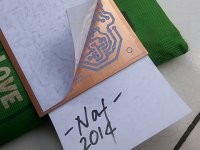
Dunk the board in cold water for a minute, then peel it. It should come off clean, leaving blue stuff on top of all the toner. Don't remove that, the toner and the blue stuff together is the etch mask.
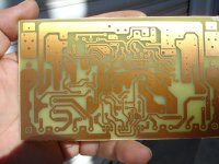
So far I've done a couple of reasonably large one-sided boards this way, and the masks look very good!
This laminator is adjustable. Backing off the adjusting screws about a full turn from the factory setting allows it to accept a .062" thick board.
I clean the boards toothpaste and green scrubby sponge, then rinse, dry, and clean with acetone and a paper towel. Keep rubbing until gunk stops coming off on the paper towel. Keep fingerprints off the board now...
Print on the dull side of the press-n-peel with a laser printer, as much toner as it'll let you apply.
Run the board through the laminator in a plain paper jacket a few times to warm and dry it, then run it through sandwiched with the press-n-peel about 10 times. I set the laminator for 300 degrees F.
Dunk the board in cold water for a minute, then peel it. It should come off clean, leaving blue stuff on top of all the toner. Don't remove that, the toner and the blue stuff together is the etch mask.
So far I've done a couple of reasonably large one-sided boards this way, and the masks look very good!
I managed to etch a board using vinegar, salt, and H2O2. It took a long time, like 2 hours or more. There must be a better way...
This was a large board (4"x6") clad in 2oz copper, so there was perhaps a lot of copper to remove. This was the process:
Get a plastic tub. Add 4 ounces 3% H2O2, 4 ounces 5% distilled white vinegar, and maybe 1 tablespoon of salt. Stir. Add the board, copper side up. Agitate. Brush the board with a soft brush occasionally to remove the precipitate. (I used a toothbrush.) Add more salt if fizzing stops. If adding salt doesn't do the trick, discard this bath and make a new bath. This works wonders! With each new bath, it would start fizzing energetically. Over the next 10 or 15 minutes, this fizzing would fizzle to a slow bubble and then to nothing. Salt might bring it back for another 5 minutes, once, maybe. Then to go any further, you need a new bath.
After about 5 baths, the etchant finally ate up all the copper. In hindsight, I would try harder to have more PCB surface area covered in copper so there's less to remove, to require less etchant.
Now I've got an old laundry detergent jug half full of used-up etchant to safely dispose of. That's a whole 'nother issue...
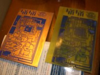
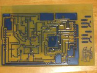
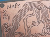
First pic here is a before-and-after for the etching process. Second pic gives a better idea the detail level here. It's a single sided board, and except for an SMT opamp adapter (in the corner) the traces are all 25 mil or more.
This was a large board (4"x6") clad in 2oz copper, so there was perhaps a lot of copper to remove. This was the process:
Get a plastic tub. Add 4 ounces 3% H2O2, 4 ounces 5% distilled white vinegar, and maybe 1 tablespoon of salt. Stir. Add the board, copper side up. Agitate. Brush the board with a soft brush occasionally to remove the precipitate. (I used a toothbrush.) Add more salt if fizzing stops. If adding salt doesn't do the trick, discard this bath and make a new bath. This works wonders! With each new bath, it would start fizzing energetically. Over the next 10 or 15 minutes, this fizzing would fizzle to a slow bubble and then to nothing. Salt might bring it back for another 5 minutes, once, maybe. Then to go any further, you need a new bath.
After about 5 baths, the etchant finally ate up all the copper. In hindsight, I would try harder to have more PCB surface area covered in copper so there's less to remove, to require less etchant.
Now I've got an old laundry detergent jug half full of used-up etchant to safely dispose of. That's a whole 'nother issue...
First pic here is a before-and-after for the etching process. Second pic gives a better idea the detail level here. It's a single sided board, and except for an SMT opamp adapter (in the corner) the traces are all 25 mil or more.
Attachments
I can get a good toner transfer, using an Apache AL13P laminator and "Press N Peel Blue" transfer paper.
Give glossy presentation paper a try (not photo paper). I get perfect results with it and it's way cheaper than PNP. A $30 pack will last a lifetime.
point-to-point can be done neatly, perf board, with patterns, ground planes, pth...
even "dead bug" can give very good performance http://cds.linear.com/docs/en/application-note/an47fa.pdf
even "dead bug" can give very good performance http://cds.linear.com/docs/en/application-note/an47fa.pdf
my own pcb
If you like this result you would be see here for details:http://www.diyaudio.com/forums/solid-state/221741-dx-blame-st-together-dx-super-116.html
Post#1152
If you like this result you would be see here for details:http://www.diyaudio.com/forums/solid-state/221741-dx-blame-st-together-dx-super-116.html
Post#1152
Attachments
Last edited:
- Status
- This old topic is closed. If you want to reopen this topic, contact a moderator using the "Report Post" button.
- Home
- Design & Build
- Construction Tips
- Making my own PC boards