I would like to ask Edmond kindly if he has built some of the circuits shown in his webpage
Super TIS
or are all these circuits just in simulation. Thank you, Edmond.
Hi Pavel,
The SuperTIS has been built by Philipp Gutknecht, see this post. Also the PMP and MCP amps has been built by a few other people (with success).
Cheers, E.
The SuperTIS has been built by Philipp Gutknecht, see this post. Also the PMP and MCP amps has been built by a few other people (with success).
Pretty pictures, can you share some results beyond nice wordings?
Pretty pictures, can you share some results beyond nice wordings?
I don't know what circuits you refer to, but more can be found here: http://home.tiscali.nl/audio/
\\\Jens
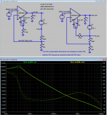
Hello EdmondPlease, see below for an example of OIC (from E.M. Cherry, J. Audio Eng. Vol. 30, No. 5, 1982 May). In this case the compensation capacitor is placed between the VAS-input and OPS-output.
Well, I think I'd call that attempted-OIC, because I've yet to see an example of it that was stable in the real world.
TMC is different: There is no direct (pure) capacitive path between the VAS-input and OPS-output. TMC also behaves differently: At AF it behaves roughly the same as OIC, at HF however, it behaves more like ordinary Miller compensation. Because of the transition between these two modes, it's called (at least on this forum) Transitional Miller Compensation.
Whereas I've always called that OIC that works. I do appreciate the transition introduced by the network (there's plenty about it in APAD6) but since ordinary Miller compensation already has a transition in that global NFB is transitioned to purely local NFB, I don't find TMC a helpful description.
BTW, at first instance, I also believed that TMC was just a 1-pole system, but JCX et al have convinced me that it is indeed a 2-pole system.
Which brings me back to my question- what implications (if any) does the 2-pole issue have for practical design?
Cheers, E.[/QUOTE]
look at the loop gain with the probe cutting both the global and T resistor feedback loops around the output stage and you see the total loop gain around the output stage looks every bit as much "2-pole" "inside" TMC as with "conventional" 2-pole
you then design the 2nd order slope loop gain breakpoint a sufficient distance below the unity gain intercept to not degrade the phase margin too much - exactly like compensating the ordinary 2-pole when all the gain is visible in the open loop, by just cutting the global feedback loop
you then design the 2nd order slope loop gain breakpoint a sufficient distance below the unity gain intercept to not degrade the phase margin too much - exactly like compensating the ordinary 2-pole when all the gain is visible in the open loop, by just cutting the global feedback loop
Attachments
Last edited:
Hello Edmond
[..]
Hello Douglas,
Following the same resaoning, calling it OIC is even less helpful, as that acronym is alraedy taken for something else. Anyhow helpful or not, TMC is the de facto and established name for many year. Substituting it for something else creates nothing but confusion.Whereas I've always called that OIC that works. I do appreciate the transition introduced by the network (there's plenty about it in APAD6) but since ordinary Miller compensation already has a transition in that global NFB is transitioned to purely local NFB, I don't find TMC a helpful description.
Well, jcx have already explained that (i.e. stability issues). Hope that suffice. Anyhow, the saying: "There ain't no such thing as a free lunch" applies also to this case.Which brings me back to my question- what implications (if any) does the 2-pole issue have for practical design?
Cheers, E.
Well, jcx have already explained that (i.e. stability issues). Hope that suffice. Anyhow, the saying: "There ain't no such thing as a free lunch" applies also to this case.
Nice to see you changed your opinion. It took over 3 years, but better late than never.
I'm currently working out a non switching Bryston-type OPS. Is the Bryston OPS topology patented?
Hi Franzm,
Have you seen this model? >BIGBT with MOSFET drivers<
MOSFET drivers make a lot of sense in Bryston-alike topology in my opinion.
I can tell you why, but let's better move to the right thread then (the one where the link points)
")
Cheers,
Valery
Hi Douglas,
I just received my version 6th edition...
I suspect an error in the Figure text for Figure 8.11 page 214…..
It refers to two traces where there is only one
\\\Jens
I hope you enjoy and find it useful.
Yes, the caption of Fig 8.11 is a known error. Somehow the caption for Fig 8.3 got duplicated there. For the description of Fig 8.11, see the bottom of p210.
Hello Edmond
[..]Hello Douglas,
Following the same resaoning, calling it OIC is even less helpful, as that acronym is alraedy taken for something else.
Cheers, E.
What else? Though I do note that the Orkney Islands Council seem to have got there ahead of us.
On reflection, how about OIMC? Output-Inclusive Miller Compensation is about as descriptive as you can get in an FLA. (Four Letter Acronym)
What else? Though I do note that the Orkney Islands Council seem to have got there ahead of us.
On reflection, how about OIMC? Output-Inclusive Miller Compensation is about as descriptive as you can get in an FLA. (Four Letter Acronym)
Have mercy, Mr. Self.
Of Edmond's "invention" of several years ago, all that it's left today as original work is the TMC acronym. Give him that much credit.
OIC vs TMC vs BMC
What else? Though I do note that the Orkney Islands Council seem to have got there ahead of us.
C'mon Douglas. OIS stands for Output Inclusive Compensation. Maybe you have forgotten what it means, so here is a reminder:
"Audio Power Amplifier Design Handbook Fifth Edition", page 217: Including the Output Stage: Output-Inclusive Miller Compensation, and the schematic is on page 216, fig. 8.1-C. (btw, I've also the 6th edition)
I'd rather TLA's. So what about Baxandall Miller Compensation (BMC)?On reflection, how about OIMC? Output-Inclusive Miller Compensation is about as descriptive as you can get in an FLA. (Four Letter Acronym)
Cheers, E.
Last edited:
Douglas,
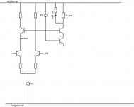
Having skimmed through the new VAS section of the 6th edition a reoccurring question comes up with respect to DC BIAS point for all of your designs. It is regardless whether the analysis is about a single ended or balanced topology.
It seems that the DC current through the VAS is not easily found unless simulated.
It also seems that the designs have the same DC and AC gain (From input to output of VAS) – is there a specific reason for this choise?
Have you examined (but not documented) the input -> VAS implementation found below?
Best regards
\\\Jens
Attachments
Last edited:
C'mon Douglas. OIS stands for Output Inclusive Compensation. Maybe you have forgotten what it means, so here is a reminder:
Cheers, E.
Um... what? OIS?
Whatever makes you think I have forgotten what OIC means in the last 12 hours????
No problem there then. Simulators are free.Douglas,
Having skimmed through the new VAS section of the 6th edition a reoccurring question comes up with respect to DC BIAS point for all of your designs. It is regardless whether the analysis is about a single ended or balanced topology.
It seems that the DC current through the VAS is not easily found unless simulated.
It keeps thing simple.It also seems that the designs have the same DC and AC gain (From input to output of VAS) – is there a specific reason for this choise?
Have you examined (but not documented) the input -> VAS implementation found below?
Best regards
\\\Jens
No. What advantages could it offer??
One is a low frequency peak in the open loop plot at around 1kHz to 10kHz.
There is also often a peak in the Closed loop plot at MHz frequencies.
Are not those two peaks the same thing litteraly.?.
I mean if on OL you have a pole at the origin and another one at 1-10khz, shouldnt, once the loop is closed, this second pole be rejected at high frequencies by the virtue of the miller loop..?.
This second pole could eventualy produce a peak at high frequencies if the output stage is slow enough such that the return ratio is smaller at this frequencies.
With TMC the peak doesnt appear as at the relevant frequency the miller loop is already closed around the VAS while with TPC the global feedback loop frequency response is wider, that is, there s more GNFB at said frequencies in this latter case, the feedback (global + local) around the output stage being the same in both cases.
Are not those two peaks the same...
I don't believe so
I mean if on OL you have a pole at the origin and another one at 1-10khz, shouldnt, once the loop is closed...
When you say "Open Loop" you need to be bit careful about which loop is open and once any loops are closed you need to be careful about what gain you mean.
We can start with no compensation and the outer loop open.
When you close the Miller loop the poles so-called "split".
When you close the TPC compensation loop there is not a pole at the origin and one at 1-10 kHz, there are two poles at 1-10 kHz - and typically a peak. This is already equivalent to the "split" pole miller case.
Once you close the outer loop then any peak in the closed loop response is determined by the behaviour at and above the Global ULGF. This is unrelated to the 1-10 kHz behaviour.
The TMC case is similar but there is not the extra shunt load on the VAS/TIS that TPC imposes. That shunt load is (mostly) bootstrapped away by the OPS. I suspect that matters more than some people realize.
Best wishes
David
Last edited:
- Status
- This old topic is closed. If you want to reopen this topic, contact a moderator using the "Report Post" button.
- Home
- Amplifiers
- Solid State
- Your opinions are sought on Audio Power Amplifier Design: 6th Edition. Douglas Self