Hi guys,
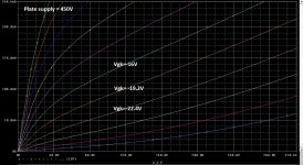
How to get the ultra-linear anode characteristic curve for the EL34 tube? I had found one on google for Vs = 450V at 43% tap.
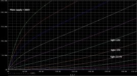
However, my design spec is Vs = 300, at 40% tap.
Would it be possible to obtained the characteristic curve from simulation(LTSPICE)? Or is there a better technique to approach this problem?
How to get the ultra-linear anode characteristic curve for the EL34 tube? I had found one on google for Vs = 450V at 43% tap.
However, my design spec is Vs = 300, at 40% tap.
Would it be possible to obtained the characteristic curve from simulation(LTSPICE)? Or is there a better technique to approach this problem?
YesWould it be possible to obtained the characteristic curve from simulation(LTSPICE)?
I might be told off for this . It hardly makes any difference. I had a transformer that allows 82%. That really seems excellent. Almost like triode yet better gain. Triode is inferior but usefully so. The voltage will be the bigger problem as you are asking the tube to work with less voltage to reduce it's distortion. In some unusual applications EL 34 can work at 800V. Siemens cinema amps did. Class A2 pentode 9dB feedback and 100 watts from a pair. 2 x EF 41 drivers in long tail pair I think like Quad.Hi guys,
How to get the ultra-linear anode characteristic curve for the EL34 tube? I had found one on google for Vs = 450V at 43% tap.
However, my design spec is Vs = 300, at 40% tap.
Would it be possible to obtained the characteristic curve from simulation(LTSPICE)? Or is there a better technique to approach this problem?
One thing that might help you. I detest UL amps. I thought I did. Then I built ones without loop feedback (output to some section inside amp). On investigation I love UL and not loop feedback. GEC knew why and gave advice on ringing. They had special networks to the UL taps.
I supect up to 6dB loop feedback you might be OK? After that spectrum analyzer to the ready and forget simulators as they have no reliable model of the output transformer.
EL 34 is a wonderful valve and will help you greatly. The best example of a UL amp I know of is Dynaco A70. The 7199 valve is non existent. That is not the point. The transformers and components did not cause any problems. It shows it can work and excel.
You might get away with 180 mA shared cathode current per pair. As I have no idea what resistor I would use a LM317 as current sink. 1.25V/0.2 => 6.25 R from memory. EL 34 is taken to be about 27 watts maximum dissipation. I am assuming 27V loss. If so 7R5 seems where to start if push pull amp.
Hope this helps.
Ultra Linear Operation
ultra-linear
It hardly makes any difference.
I agree, not much difference between 40% vs. 43%... Just use the 43% curves and scale them based on the new Eg2. The scaling factor could be found in RDH4.
This is worth a read.
Ultra Linear Output Transformers
This also and answers your question very well.
http://www.r-type.org/articles/art-139.htm
Ultra Linear Output Transformers
This also and answers your question very well.
http://www.r-type.org/articles/art-139.htm
Last edited:
Thank for the information sources guys, they are very helpful.
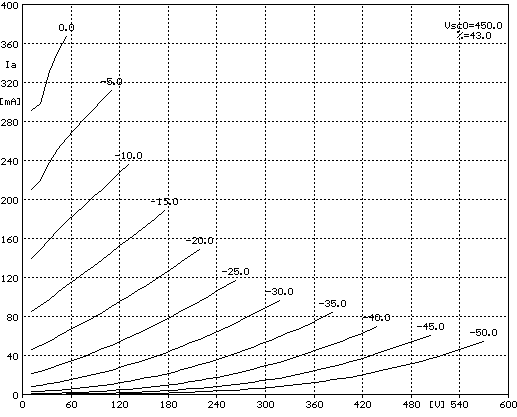
However, I am still searching for the plate characteristic waveforms of the EL34 in ultra-linear mode. Without this information, I cannot draw my load-line, thus I can't work out my DC quiescent operating point.
I have tried to simulate the plate characteristic waveform in PSpice as seen below. The result shows that different plate voltage(e.i. 300V vs. 450V) generate different characteristic waveforms. This is my first tube amp design, thus I don't have much experience. Please could someone confirmed these results.
Attachments
Last edited:
Just use the 43% curves and scale them based on the new Eg2. The scaling factor could be found in RDH4.
Could you please elaborate more on this point??
You are on the right track, varying the screen grid voltage should change the plate/screen current. SPICE makes the process very easy, but if you want to do it manually, you can start with a traced curve set such as the one shown below:
Then to scale the curves from Eg2 from 450V to 300V, you apply a current scaling factor of 0.56 (for the details please refer to RDH4, p. 38).
Then to scale the curves from Eg2 from 450V to 300V, you apply a current scaling factor of 0.56 (for the details please refer to RDH4, p. 38).
I have been down this track myself and thought everything highly technical and I needed precise answers. Soldering it up and playing got me 2 years down the road in reading terms. It is the unknown unknowns that caught me out. I always use a spectrum analyzer and by near trial and error find the truth. Sometimes years later I find something very similar and say " that would have saved me time". The good news is set HT set cathode current and then get it working.
For example EL 34 will allow about 27 watts anode dissipation and that's all there is to know. I always think beyond that transistors are the answer as they are the real deal when wanting fast accurate information.
Given what you have it should be a days work to plot the answers . You only have current as your variable as all other parameters are fixed if I understood correctly. You can have a triode option. Also decide on negative feedback which should include none. EL 34 unlike any other valve I have tried is always giving more or less the same regardless. It has to be hopelessly wrong for it to be wrong. All EL34 I measured are mostly the same. That isn't the impression when listening. DC heater gained me very little over hum-bucked centre tapped. A high grade PSU was the big factor.
40 years ago I was doing the maths for this at college. Mostly I have never done it since because it is the hardest route I know of. The worked examples usually exist.
Last edited:
In Ireland and France it is considered mildly impolite to ask directions. There is a way. If you ask incorrectly you might be told " I wouldn't start from here ".
I wonder if your question is saying " should I start from here " ? Possibly not. The boring route is sometimes better . As valves are not hyper hi fi it hardly matters . GEC published many designs at many voltages for KT88. Mostly they were the same. For what it is worth EL34 is better to my ears. Let's make that clear. EL 34 a bit wrong is still better. Avoid ultra linear oscillation at all cost . I would think you are 90% likely to have that. It makes voices sound nasal and nothing really obvious apart from that if no analyzer used. Clear the problem to have the sound of Dynaco. Going Triode is often a rescue. Forget load lines for triode, it will work. You don't know accurately the dynamic impedance of your speakers I would guess ? That means the most, it might be 2 ohms somewhere when stated 8. I made my PP EL34 10K anode to anode so as to do anything. I lost a couple of watts.
When a valve ages it is acceptable years after the technical side is falling to pieces. The simple resistor bias is actually better at working when valves age. Forget fixed bias if you want trouble free working.
I can support Nigel Pearson's last two posts.
Reading up will show that there is nothing critical about UL despite some anecdotal tales to the opposite. Then there are many sets of tube characteristics for EL34 on the internet regarding distortion and such vs. screen taps and output (please excuse my not selecting such here for you now; they are easy to find).
They mostly show best performance (but as said not critical) for 43% taps, 1K series screen resistors and some 6,600 ohm load - I cannot recall the cathode current now. Like you I am also prone to calculating/plotting things; but the saying goes: "Experience is a good tutor, but second-hand is cheaper!" Something like: 'Don't re-invent the wheel.' You can really spend your time/initiative better than painstakingly re-plot a power stage around the above points.
(PM: I would pay attention to the Langford-Smith and Chesterton articles quoted above. Later if you want, you can also look up a KT88 design with full tube characteristics appended. It is rather different than for the EL34. That I will try find for you later and quote here.)
A simple question. Why 300V? I very much doubt the transformer is critical up to 450V. Hard to say without knowing more. To add to the PSU is cheap enough.
I used 43% and 10K anode to anode to give me better triode results. I rather like 80% UL taps as it looks exactly like triode yet gives more gain.
Do not overlook pure pentode if using feedback. Not my cup of tea, interesting and very powerful.
My suggestion is the real life curves will look very similar and would at a guess add 20% more distortion as the HT is lower. It would be acceptable compared with loudspeaker distortion.
One of the weirdest suggestions is to put a forward biased 1N4007 diode between UL tap and g2 of each valve. The author said it helped deal with speaker back EMF. He and I found it does not show in measurements. His assertion being that the sound is less fizzy. A friend warned me off as he said it could form a voltage doubler. At 300V one might be safe if EL 34 ( that is assuming 600V, it could be more , surely g2 causes that anyway ) . Also Gu50. GEC mention cross coupling in UL g2 grids and how it is a big problem. I love SE UL and it might be better from this point of view. The diodes might help. I do suspect the UL does at times get close to the limits when 450V at the anode tap. A pentode EL 34 amp I had was at 820V due to my home not being 220V, the lovely blue colour in the valves was very attractive. East German National brand ( bit of oxygen in the valve ? ). Fitted with Siemens 34's was fine. 1950's 100 watts cinema amp made by Siemens. The g2 was from a choke PSU at about 400 V and raw DC to the EL34 anode. 2 x EF 41 ( ? ) and 9 db feedback. Distortion was 1.3% at 10 watts and 0.2% at 1 watt. 1 watt in a cinema is a typical dialogue level. The 13% at 100 watts for explosions etc. Still class A mostly. It had a tap for 8 ohms. Hard to say what the sound was like as it was 100 V line for a proper test. Not bad through the test winding. A bit grey.
I asked a German designer why we dispute RIAA curves to +/- 0.05dB. To which he said " at least something should be right". I thought this is where being too close to a problem forgets what we are doing. However, I totally understand.
If you buy a cheap spectrum analyzer or adapt your sound card you might in 10 minutes have answers. I would use a LM317 variable current sink and ensure my tubes are matched before I start. For measurements cheaper tubes will give good data. Ruby EL 34 seem good value in UK. They can be bought in matched quads. If you find 80% dissipation works well you should have a long lived amp. Tube Cad has a variable bias option if wanting transient power. Personally speaking the LM317 comes out at the end of tests to be replaced by a double wattage resistor well soldered in . If the resistor required is 5 watts make it an 11 watt. If two 1 R resistors are added to the cathodes you might measure balance ( via a 3 pin DIN ). You can make the volt drop 2 V and fit 2 x LED and dropper resistor to show equal brightness. Quad said the eye is sensitive to 1 part in 10000, not bad for 10 pence. Check with voltmeter the initial balance if so. I dare say 1.5V filament bulbs would be better ( 0.15 watt). Above 2 V I suspect it will alter other parameters. Now lets say this clearly. As much as anything matters greatly the balance is the most important.
Euphonic Distortion: Naughty but Nice? | Stereophile.com
Hi guys,
How to get the ultra-linear anode characteristic curve for the EL34 tube? I had found one on google for Vs = 450V at 43% tap.
However, my design spec is Vs = 300, at 40% tap.
Would it be possible to obtained the characteristic curve from simulation(LTSPICE)? Or is there a better technique to approach this problem?
My opinion is that if we want to generate in Spice has a UL pentode should keep in mind that the installation voltage UL Ug2 is greater than the voltage on the anode, due to the DC resistance of the output transformer coils.
Where to power supply + Ua,example 400V, 385V anode and had about G2 would be around 295V, DC resistance depends heavily on output transformer coils, but can be approximated, and I think we can draw characteristics very good.
Last edited:
If this was me and I had the parts I would BUMP the voltage . We often did this on TV's. To bump 100V is easy. Add PSU's like batteries. Mostly it works when sensible voltages. When building a 1000 V PSU it is often the best.
UL is very complicated. I don't think pentode voltages tell us much. Suck it and see is the best.
A blind girl asked what colour was like. After months of thinking her companion said the sun might represent red if the heat. We have no need to be blind.
I used to set up engines. Mostly I found I could with rules in place do it by ear. Recently a young lady brought me her Suzuki Jeep to fit a distributor to ( Nige might be able to do it I suspect she was told ). No data and she needed to get home 50 miles away. I put my finger on the plug holes to get compression to set the cable position. I used a lolly stick to get the stroke. I calculated 5 degrees BTDC and set the points as best I could. When taken to the garage it was exactly to book spec. 5 BTDC usually works regardless , 8 is a risk. This is called static timing. Triumph motorcycles were 38 degrees full advanced and 42 degrees racing. The timing was a balance of cam wear and best static position. Seldom was it very accurate. It was judging what was best. Advanced was usually done with a strobe. I jammed the advance and did it as if static. Far easier. Often I found a 2 degrees discrepancy that way which was allowed for. If I set the timing so it was 40 degrees worse case and ignore the static position it worked fine. The carburation could be set rich on pilot jet if the static a bit wild as the advanced state is 90 % what we need. This might put the static at 6 and 3 degrees which would seem impossible. What you don't want is 9 and 6. Amplifiers are the same.
I read the mildly rich pilot jet gives reduced fuel consumption. This is because to cleanly accelerate is important. It also feels nicer to take 1 less second. If the engine idles it will have slightly black plugs. What you do is run full bore and cut the engine and put in the clutch. Often the plug would say hole in the piston white. One then had to do a plug chop at realistic speeds. An engine like this will fail emissions if modern tests yet use less fuel ( 5% ) .
Last edited:
My opinion is that if we want to generate in Spice has a UL pentode should keep in mind that the installation voltage UL Ug2 is greater than the voltage on the anode, due to the DC resistance of the output transformer coils.
Where to power supply + Ua,example 400V, 385V anode and had about G2 would be around 295V, DC resistance depends heavily on output transformer coils, but can be approximated, and I think we can draw characteristics very good.
*************************************
Sorry! rectify: "Where to power supply + Ua, example 400V, 385V anode and HAD about G2 Would be around 395V"
Would love to see the curves as it is very interesting. When I did this, I just did it . As distortion is high anyway I never thought much about it. Curve looks OK , job done.
In my case I did 3 very bad things. 4 x EL 84 to replace 2 x EL34 ( in V8 look ). Said to myself the power is current x voltage , used higher current (80mA) and guessed it was OK. Ignored the fact that EL 84 likes different UL points. Was the only show in town so to speak so used what I had, or don't bother. I too used 320V and 43%. I even used direct rectified mains electricity for data (don't please). My interest was 10V rms to drive it rather than 25 Vrms. With EL 34 triode is possible EL84 looks more difficult although said to be very good.
In my case I did 3 very bad things. 4 x EL 84 to replace 2 x EL34 ( in V8 look ). Said to myself the power is current x voltage , used higher current (80mA) and guessed it was OK. Ignored the fact that EL 84 likes different UL points. Was the only show in town so to speak so used what I had, or don't bother. I too used 320V and 43%. I even used direct rectified mains electricity for data (don't please). My interest was 10V rms to drive it rather than 25 Vrms. With EL 34 triode is possible EL84 looks more difficult although said to be very good.
Last edited:
Hi Nigel !
Check nr1 circuit from this link Analog Audio Amplifier Design, I think that is the best & optimum way to go when we want to made some EL34 PP / UL OPS circuit , special with this new and not so good EL34s , where G2 is suplied from 1/2 of B+ ( center tap of main power transf. secondary ) and AC modulated via separate OPT coil winding , Actually this various new production EL34s will work the best with max. B+ plate = 500VDC / B+ G2 = 250VDC .
BTW , I like your thinking and approach about four stroke engines , just want to ad next : optimum firing point ( static & dynamic ) generally depends directly from internal shape of combustion chamber which directly determine max.compression ratio and on the other side is just fuel quality (octane nr. ) .
Check nr1 circuit from this link Analog Audio Amplifier Design, I think that is the best & optimum way to go when we want to made some EL34 PP / UL OPS circuit , special with this new and not so good EL34s , where G2 is suplied from 1/2 of B+ ( center tap of main power transf. secondary ) and AC modulated via separate OPT coil winding , Actually this various new production EL34s will work the best with max. B+ plate = 500VDC / B+ G2 = 250VDC .
BTW , I like your thinking and approach about four stroke engines
, just want to ad next : optimum firing point ( static & dynamic ) generally depends directly from internal shape of combustion chamber which directly determine max.compression ratio and on the other side is just fuel quality (octane nr. ) .I understand you built your own motorcycle? My old boss also in 1937. 5 degrees is the "all unknown route". My great Uncle was friend of Harry Weslake who patented gas flowing. Alas I never met him. Diesel engines become chaotic when super powerful and give destructive piston failure. Cure is to simultaneously inject coiling oil with the main injector sequence under the piston crown!! No maths has ever solved this. This would be 1000 rpm large engines running high compression and supercharging. The fix is empirical and works.
That amplifier link seems to be the ultimate Dynaco. I had no idea that was possible.
I hope my next explanations is not too stupid or obvious. The curve of a triode or pentode is much like a piece of elastic rope. As you pull it to be longer it assumes a near straight line. To make it more realistic lets say the rope is heavy so assumes the curve shape easily. That is high voltage doing it's magic.
I looked at synthetic UL using a buffer transistor. Seemed too complicated. The author liked the EL34 for my reasons. That pleased me.
Nigel
Yes I have build few motorcycle , my next project is motorcycle based on naked Citroen 2CV / 601cc engine with associated 2CV gearbox , just one simple old school bobber bike .
Constant underneath piston cooling with beam of oil from regulated oil jet is already old design solution , many modern turbocharged diesel engines use that method , same as many modern Japanese heavy ballasted motorcycle engines , actually without that piston oil cooling all that engines will never survive since piston thermal ballast and piston material dilatation will be way to high .
About UL OPT with separate tetriary coil windings for G2s I would not go with fixed three taps at let`s say standard proposed 43% ratio , with one B+G2s input and two opposite phase outputs , but with one B+ input and several different G2 outputs , for example output taps at 20 % , 30 % , 43 % , 50 % and 80 % of G2`s AC relative modulation .
Later I will found empirically what G2`s taps the best suit against my real life loudspeakers dynamic impedance change . I think that is special good praxis for custom build UL OPT `s with tetriary G2`s windings .
- Status
- This old topic is closed. If you want to reopen this topic, contact a moderator using the "Report Post" button.
- Home
- Amplifiers
- Tubes / Valves
- Ultra-linear plate characteristic curve for EL34