Awesome thanks a lot Erik
Quick question. Is the motor shaft snug enough in the 2mm hole?
I got a new meter and I measured the motor shaft at 1,85mm
I am making a turntable one out of ebony, currently working on an MDF test
I guess it all depends on the material you use...
Are you making the puckplatform out of ebony as well ?
Thanks Dimitri.
Swapping the leads did it. It now goes in and starts looking for TOC. The laser alters the height as it tries to find out if there is anything to read. Then 00 appears on the LCD. The sad thing is that it shows 00 even if I put in any CD. No tracks? Don't believe so. Is the laser beam in visible spectrum - can it be determined that the laser works if in a dark room?
Yes, the static protection blob is removed.
The special puck... It takes to much force to use it as the fit is very tight! I dare not use it so I use the original magnetic one.
So these are my woes for the moment.
Regards
Laser is not in visible spectrum, use a camera or phone to see it, right on top of laser beam.
See also if distance between turntable and mech base was not altered- should be 19.4mm
Regards,
Tibi
Thanks Tibi. I checked with my phone and there is a faint reddish glow.
Yes the distance from mech to top of platter is 19,4mm.
Is there a schema of the main board?
Regards
Last edited:
Thanks Tibi. I checked with my phone and there is a faint reddish glow.
Yes the distance from mech to top of platter is 19,4mm.
Is there a schema of the main board?
Regards
If you mean component placement see attached files. Anyhow I recommend to follow high resolution pictures from my web site.
If you mean Shiga MKII schematic, this is not public. As you purchased full kit, you should got one in printed format. If not I'll send you a copy.
What do you expect to see on schematic ?
Regards,
Tibi
Attachments
Last edited by a moderator:
Thanks Dimitri.
The special puck... It takes to much force to use it as the fit is very tight! I dare not use it so I use the original magnetic one.
Regards
+1
I reveived the puck today and in order to make use of it without stress on the spindle I will have to make adjustments on the platform.
I first tried the puck on five other platforms to make sure that there are no platform deviations causing the problem...there are not.

So at the moment I am thinking of widening the plastic gap of the platform just a little or shaving the aluminim a little...since unfortunately the puck is not useable at the moment.
Yes kind of like your delrin thingy, but with a simpler design
The best thing when using ebony is make a really tight fit and take care that it is open on the top (compressed air !)
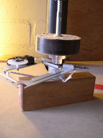
I think you shoud build yourself a tool to press the platform home in order not to bend the spindle.
I am very curious if you manage to get the job done...succes
Btw I have somewhere a picture of my home built tools and with the help of a drillplatform you have total control over the situation.
If you mean component placement see attached files. Anyhow I recommend to follow high resolution pictures from my web site.
If you mean Shiga MKII schematic, this is not public. As you purchased full kit, you should got one in printed format. If not I'll send you a copy.
What do you expect to see on schematic ?
Regards,
Tibi
I wish to follow the laser traces as a starter. I didn't receive the shematic on paper so please resend - prefereably in electronic format (picture is ok if it is good quality).
What else can I do? Ok, there is a possibility that the transport is ruined as something has happened to its gear. So another one should be on its way and hopefully everything will work. If not? Then I need a schematic to hunt down whatever error is stopping it from functioning.
One question is only half answered - the cd door cabling. Ok, from danzups post I learned which pin is #1. So is it 1 to 1, 2 to 2 and 3 to 3?
The motor cable was 1 to 6, 2 to 5 and so forth. I didn't expect that and couldn't find info on the issue from drawings, pictures or posts.
Any help is most welcome.
Regards
I have widening the plastic gap with sandpaper wrapped to a driller.
Regards,
Rudy
Thanks Rudy. I'll either do that or as Tibi wrote shave the Al-puck.
Stability is pivotal so I don't want to introduce unwanted vibration.
Regards
The best thing when using ebony is make a really tight fit and take care that it is open on the top (compressed air !)
The funny thing is that no matter what material I try, I keep returning to my MDF puck...
Anyway... I have sent the final plans to my engineer. I hope to get the test platform within the week
I wish to follow the laser traces as a starter. I didn't receive the shematic on paper so please resend - prefereably in electronic format (picture is ok if it is good quality).
What else can I do? Ok, there is a possibility that the transport is ruined as something has happened to its gear. So another one should be on its way and hopefully everything will work. If not? Then I need a schematic to hunt down whatever error is stopping it from functioning.
One question is only half answered - the cd door cabling. Ok, from danzups post I learned which pin is #1. So is it 1 to 1, 2 to 2 and 3 to 3?
The motor cable was 1 to 6, 2 to 5 and so forth. I didn't expect that and couldn't find info on the issue from drawings, pictures or posts.
Any help is most welcome.
Regards
On Shiga there is not so much to hunt. If everything was properly soldered and all parts have been soldered with care, than will work from very first run.
A cracked capacitor may ruin you entire project and is very hard to locate.
Cd door cabling is 1-1, 2-2, 3-3.
Shiga will work even without CD door cable. Power on Shiga with a CD on and will read TOC. Obviously if you change CD than you need to perform power cicle in order to get TOC read again.
On motor cable if you look on CD mechanic you'll see that motor connector have pin 1 marked. All you had to do was to make a cable who respect pin 1 from main board to go to pin1 on CD mechanic.
Now back to your problem.
Check if you have laser light durring TOC reading. If not, than you have a ribbon cable problem or this do not make proper contact with connectors. Double check this.
If you have laser light, than check soldering again and look for a possible cracked capacitor.
Regards,
Tibi
Last edited by a moderator:
I'll check tomorrow. I'm not sure it can be checked on the pics I posted earlier on the first pages...
Regards
I had a look again and seems to be 2N4403 - ( marked PJ66)
I'm not sure if R46 is proper soldered.
And please make again few high resolution pictures. Try to use macro when you take pictures and get better focus. I want to see ribbon connector and ic's pins.
Regards,
Tibi
- Home
- Source & Line
- Digital Source
- Shigaclone MKII Black - The builders Thread