Possibly. Getting those transformer leads twisted will likely do more.
Check the resistance from PSU ground to the chassis. It should be on the order of 10 ohms. Significantly less and you have an issue such as an input jack that isn't isolated.
Did you resolve the issue of mosfet Drains being shorted to the case? Or was that the 260 ohm reading?
Both primaries and secondaries have to be twisted?
Psu gnd - Chassis = 14 Ohm OK
Gate - Chassis = 154 Ohm
Drain - Chassis = 42 Ohm
Source - Chassis = growing (capacitors charging?)
All these measurments with power off.
Now I'm measuring the diodes boards.
Yes, all leads of any kind should have supply and return twisted together. As suggested earlier, even a little twist is better than two wires of a pair running a cm apart.
Yes, PSU ground to chassis looks good.
Mosfet drains are the pins that have the potential to short to the chassis. Your measurement looks OK - CL60 plus the feedback network makes pretty close to 42 ohms.
Yes, PSU ground to chassis looks good.
Mosfet drains are the pins that have the potential to short to the chassis. Your measurement looks OK - CL60 plus the feedback network makes pretty close to 42 ohms.
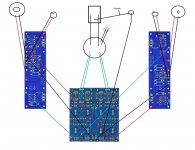
First pic is your design. Note that the grounds and the input cables form a loop around the entire guts of the unit. Connecting the source using two IC's completes that loop.
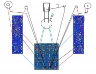
Second pic shows running one of the input cables, the right in this case, by wrapping it around the ground (green) to the common at the supply board, then the ground to the other channel, then to the left input jack, to the right input jack. Note that this arrangement gets rid of the loop in the power amp chassis. (pardon the crudity of my model)..
Note that you must wrap the external IC's around each other as well.
jn
Why should I use this arrangement and not the original one?
LOOP AREA
I asked because I didn't understand the practical scheme and I want to try.
Googling I've found this grounding scheme:
"New solution: connect L input Rca ground to L black speaker out, do same on Rhs. Connect the two black speaker outs with a wire. Connect the centre of the wire going between black speaker outputs to the ground on the power supply. Connect the power grounds on each f5 board to the same ground point on the power supply that you just connected the input and output terminals to. DO NOT use the input and output ground points on the f5 boards. The f5 board should be connected to ground with only 1 cable."
It works if I connect the wire from black speaker to psu gnd on the same side emiboard (psu is splittable) and it works only for one channel a time
Thanks. I (not the expert here) see no problem if that's what you have. Don't remember - did you try using the "Star" approach by using the power supply board as a common central ground connection? In the PC build guide it's suggested to try both methods to determine which is quietest.
This is a full (extreme) star ground. Not sure it's a best practice for the F5, but something similar was successful in the BA build shown in post #14122
Attachments
This is a full (extreme) star ground. Not sure it's a best practice for the F5, but something similar was successful in the BA build shown in post #14122
Can this scheme affected the mosfet?
I'd wait for a final call from one of the Gurus - but if properly constructed, the whole Pass DIY offerings are quite similar with the star ground often recommended. It's my understanding that a builders choice of ground placements essentially resolves to a common link. You might want to PM Bob E or 6L6 just to be sure.
Can this scheme affected the mosfet?
No. I've used the exact scheme with a few amps and it works wonderfully. (Although normally I would take the RCA ground to the amp PCB, not the PSU, unless it's quieter that way... which sometimes it is.)
I normally use what you posted here:
http://www.diyaudio.com/forums/pass-labs/121228-f5-power-amplifier-1417.html#post3941459
But because we don't have safety earth in most installations here in DK and because I am reckless, I don't make a connection from psu gnd to chassis.
I also agree that you could have wired the transformer more tight, but I have made crazier implementations with no hum. I think you have either a few burned or misplaced components or you have made an unintentional connection somewhere. Have you checked for continuity of your rca plugs to chassis?
I would normally scope such a problem if you get 50 hz noise, it is most likely a ground issue and if you have 100hz it is more likely your supply rails that go into your audio path.
Thanks cviller,I normally use what you posted here:
http://www.diyaudio.com/forums/pass-labs/121228-f5-power-amplifier-1417.html#post3941459
But because we don't have safety earth in most installations here in DK and because I am reckless, I don't make a connection from psu gnd to chassis.
I also agree that you could have wired the transformer more tight, but I have made crazier implementations with no hum. I think you have either a few burned or misplaced components or you have made an unintentional connection somewhere. Have you checked for continuity of your rca plugs to chassis?
I would normally scope such a problem if you get 50 hz noise, it is most likely a ground issue and if you have 100hz it is more likely your supply rails that go into your audio path.
I have safety equipment in my home,
Which components are burnt or misplaced? Rca are isolated from chassis.
I dont't have an oscilloscope...but I remember I checked for dc in speaker output and it was normal.
Hard to tell which components could be causing it, but I just looked at jneutrons diagram and I think it would be worth a shot. If I were you, I would take the amp apart and structure it like the stock F5: 6moons audio reviews: FirstWatt F5
You only need to heatsink your two channels and the diode boards - everything else can be lying on your workbench if it is not conductive...
You only need to heatsink your two channels and the diode boards - everything else can be lying on your workbench if it is not conductive...
What's the difference with the design I used? Isn't my build a stock f5?Hard to tell which components could be causing it, but I just looked at jneutrons diagram and I think it would be worth a shot. If I were you, I would take the amp apart and structure it like the stock F5: 6moons audio reviews: FirstWatt F5
You only need to heatsink your two channels and the diode boards - everything else can be lying on your workbench if it is not conductive...
.... If I were you, I would take the amp apart and structure it like the stock F5: 6moons audio reviews: FirstWatt F5...
I was writing a long winded post saying the same as cviller.
 No matter if the build is "stock" or not, you are at that point where disassemble/reassemble is most logical. One step at a time - one channel at a time. Sounds like a lot of extra work, but often we have to go that far back to reveal the problem..
EDIT: Also - please remember lots of the Pass designs can be mixed and matched into many uniquely configured amps. It's not the same as a 'kit' with one set of instructions.
Last edited:
- Home
- Amplifiers
- Pass Labs
- F5 power amplifier