Hi Rick,
It's early in the morning and I'm scratching my head over what you have said here. I'm trying to see the difference in whether the two secondaries are out of phase in the topology you are talking about. I am assuming you are talking about two, non-center-tapped secondaries, each of which is connected to a bridge rectifier to form a floating full-wave power supply. Each of those supplies has one output end connected to ground. The other side of one provides the positive rail, the other side of the other provides the negative rail. Since full-wave bridges are used, both secondaries are conducting on both peaks of the AC waveform. So I'm missing the difference in why the reversal of one of these two secondary windings would matter.
Cheers,
Bob
A cup of cowboy coffee might help, Bob. Reportedly, their definition of good coffee was really high end - good coffee is that coffee into which you throw horsehoes and watch 'em float.
To paraphrase Morgan Freeman on Discovery Channel - life in the universe starts after I've had my morning coffee.

Hi Rick,
It's early in the morning and I'm scratching my head over what you have said here. I'm trying to see the difference in whether the two secondaries are out of phase in the topology you are talking about. I am assuming you are talking about two, non-center-tapped secondaries, each of which is connected to a bridge rectifier to form a floating full-wave power supply. Each of those supplies has one output end connected to ground. The other side of one provides the positive rail, the other side of the other provides the negative rail. Since full-wave bridges are used, both secondaries are conducting on both peaks of the AC waveform. So I'm missing the difference in why the reversal of one of these two secondary windings would matter.
Cheers,
Bob
Hi Bob,
If we connect a dual channel scope to the main filter caps of the + and - supply you can see how the ripple waveform is either in phase or out of phase depending on how the secondary's are connected to the two bridges. I have found better sound when the ripple is out of phase, like you would see in a power amp with one CT secondary and one bridge.
This falls in line with Ed's power supply that uses four out of phase secondary's to cancel noise.
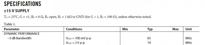
Which datasheet figure you mean, exactly?
It's in the first table, see attached.
Jan
Attachments
I won't make the tactical error to try to dislodge with rational arguments a conviction that is beyond reason - Daniel Dennett
Jan,
I love this, I have learned my lesson. I just decided that it was easier to add someone to my ignore list rather than try and use logic!
http://www.linearaudio.net
Jan,
I love this, I have learned my lesson. I just decided that it was easier to add someone to my ignore list rather than try and use logic!
http://www.linearaudio.net
Hi Bob,
If we connect a dual channel scope to the main filter caps of the + and - supply you can see how the ripple waveform is either in phase or out of phase depending on how the secondary's are connected to the two bridges. I have found better sound when the ripple is out of phase, like you would see in a power amp with one CT secondary and one bridge.
This falls in line with Ed's power supply that uses four out of phase secondary's to cancel noise.
If the pos load discharges the supply between charges, the ripple is fast up (towards more pos) - slow down.
On the negative side, it is ALSO fast up (towards more negative) and slow down.
Its a function of the charge-discharge cycle, I don't see how that can change if you swap secondary connections on one side.
Jan
Yea .... Poor, maybe wrong wording ...."Because one winding handles the positive (output peaks)
while the other handles the negative. If they are not phased
correctly they are in a sense fighting each other ..."
But if both supplies use full wave bridges, there can be no imbalance between the mains half cycles.
Please explain yourself further, with a diagram.
Or is this just something you heard/read?
Look at the 2 secondaries like the 2 halves of a tube
amplifier output xfmr's primaries. If they are phased
wrong the xfmr easily saturates because all the current
goes in the same direction. Same situation in the power
supply described.
yes, a consequence of slew rate limit - that's ~75 V/us even though just below the typ slew rate is given as 50 V/us
and some may sneer since you can get an order of magnitude higher slew - but especially in this case the "highly linear input stage" is expected to change the usual relation between slew rate limit and distortion - as can be seen in the 1 MHz 3rd harmonic in the distortion vs frequency figure
and some may sneer since you can get an order of magnitude higher slew - but especially in this case the "highly linear input stage" is expected to change the usual relation between slew rate limit and distortion - as can be seen in the 1 MHz 3rd harmonic in the distortion vs frequency figure
Jan, we want one ripple waveform going up ( + supply) and one going down (- supply) when viewed on a dual channel scope. The two waveforms are out of phase and cancel.
Build up two simple supplies of, secondary winding, bridge, cap and resistor load. Then connect a scope probe across each resistor and reverse one secondary feeding a bridge. The waveforms will go in or out of phase depending on the secondary connection.
Try it.
Build up two simple supplies of, secondary winding, bridge, cap and resistor load. Then connect a scope probe across each resistor and reverse one secondary feeding a bridge. The waveforms will go in or out of phase depending on the secondary connection.
Try it.
"If they are phased wrong the xfmr easily saturates because all the current goes in the same direction. Same situation in the power
supply described."
The transformer saturates?!?
You have lost me completely. Introducing a tube PP output simply adds confusion - a mains bridge rectifier is pretty simple to understand! Or maybe not ....
supply described."
The transformer saturates?!?
You have lost me completely. Introducing a tube PP output simply adds confusion - a mains bridge rectifier is pretty simple to understand! Or maybe not ....
Jan,
Out of phase ripple the rail to rail voltages shows double the ripple. In phase ripple and the rails move up and down the same or in another view the common (ground) is moving.
In high power stereo amplifiers it is common to wire the channels' power supplies out of phase. That way a unit impulse draws from both half cycles.
Slew rate, as you know, SR = Vp . 2 . Pi . F, for sine wave.
Ahh yes, I calculated for audio, but 55V/uS hits the stops just above 4MHz, hence the lower BW.
Silly me!
To my defense: I just checked out my high-voltage regulator for my direct-drive ESL amp. In goes 2300V, out comes 2150V, rock stable.
Now I need some 20k, 200W load rsistors...
Jan
Last edited:
Jan,
Out of phase ripple the rail to rail voltages shows double the ripple. In phase ripple and the rails move up and down the same or in another view the common (ground) is moving.
In high power stereo amplifiers it is common to wire the channels' power supplies out of phase. That way a unit impulse draws from both half cycles.
OK maybe we don't mean the same by ripple - I mean the swatooth-like 'ripple' resulting from fast charge-slow discharge of the reservoir caps.
What's your definition?
jan
> Forgive me for being stupid here
Me too
We need to consider the relationship of the currents
flowing in the 2 windings.......In or out of phase ....
> a mains bridge rectifier is pretty simple to understand! Or maybe not ....
This is the kind with a separate bridge on each winding
1 for +V and 1 for -V
Me too
We need to consider the relationship of the currents
flowing in the 2 windings.......In or out of phase ....
> a mains bridge rectifier is pretty simple to understand! Or maybe not ....
This is the kind with a separate bridge on each winding
1 for +V and 1 for -V
OK maybe we don't mean the same by ripple - I mean the swatooth-like 'ripple' resulting from fast charge-slow discharge of the reservoir caps.
What's your definition?
jan
Same thing. Under constant load from both rails the ripple will always be symmetric with a full wave rectifier. However under a normal load where more power is drawn from one rail for a period less than the AC lines, you will see asymmetric ripple. How you recharge the rails' capacitors will determine the behavior. As this will appear at the output as more HF distortion the perception might be less LF.
However it is my opinion that in a solid state amplifier it is the line noise reduction that is the dominant improvement.
Image or simulation would count more than words.
> That way a unit impulse draws from both half cycles.
In the same way (with a single supply) 1 channel can be
inverting and the other non-inverting.......The output pulls
from both rails at once........As I was trying to relate
(with no luck) above......It is hard to be eloquent about the
simplest things ....
In the same way (with a single supply) 1 channel can be
inverting and the other non-inverting.......The output pulls
from both rails at once........As I was trying to relate
(with no luck) above......It is hard to be eloquent about the
simplest things ....
- Status
- Not open for further replies.
- Home
- Member Areas
- The Lounge
- John Curl's Blowtorch preamplifier part II