HI Guys,
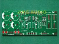
I came across these Jims Audio LM4780 boards on ebay.. LM4780 Stereo Parallel Power Amplifier PCB | eBay
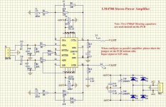
Does anyone happen to have a schematic for them? I contacted the seller but no response.
Has anyone used the same boards in the past? Any thoughts or opinions?
I came across these Jims Audio LM4780 boards on ebay.. LM4780 Stereo Parallel Power Amplifier PCB | eBay
An externally hosted image should be here but it was not working when we last tested it.
An externally hosted image should be here but it was not working when we last tested it.
Does anyone happen to have a schematic for them? I contacted the seller but no response.
Has anyone used the same boards in the past? Any thoughts or opinions?
is it:
REACTIVE LOADING
It is hard for most power amplifiers to drive highly capacitive loads very effectively and normally results in
oscillations or ringing on the square wave response. If the output of the LM4780 is connected directly to a
capacitor with no series resistance, the square wave response will exhibit ringing if the capacitance is greater
than about 0.2μF. If highly capacitive loads are expected due to long speaker cables, a method commonly
employed to protect amplifiers from low impedances at high frequencies is to couple to the load through a 10Ω
resistor in parallel with a 0.7μH inductor. The inductor-resistor combination as shown in the Figure 6 isolates the
feedback amplifier from the load by providing high output impedance at high frequencies thus allowing the 10Ω
resistor to decouple the capacitive load and reduce the Q of the series resonant circuit. The LR combination also
provides low output impedance at low frequencies thus shorting out the 10Ω resistor and allowing the amplifier to
drive the series RC load (large capacitive load due to long speaker cables) directly.
An externally hosted image should be here but it was not working when we last tested it.
Why not just ask the member to ask Jim for a schematic?I bought the assembled boards from a member of this forum who did not have the schematic, also been in touch with Jim's on eBay.
Abs
Last edited:
Why not just ask the memeber to ask Jim for a schematic?
Abs
It's worth a try
")
Better stability = better tone.Thanks Daniel, that's most helpful, at least I know what I am looking at now.
I have one board with the coil thingy and the other board only has a jumper across it. What difference if any does the coil make?
The difference is small, but useful.
thank redshift187, but I wouldnt even know where to begin, hence this post..
Is it possible to bridge this board? and what purpose does that coil thing serve?
these two posts are completely incompatible.
If you can't create a schematic from the PCB you have in your hand, you are certainly NOT capable of generating a schematic for a circuit that is inside someone else's head.
Sure, I was merely wondering if it was easily possible that's all.
Told you Dakku, they are very techy on here, and will shoot the newbies down if you post!
Thanks for posting the docs, I hope these will help a noob in same boat as me.
I guess, I asked for it by asking questions way beyond my knowledge.. But to be fair, I assumed it may be similar to audiosector design where it's a matter of putting in a couple of resistors. I might have been able to reverse engineer the board (fat chance) but it was quicker and better to ask someone, so I did
I haven't plugged them in as yet, need to decide on a case first..
In order to get the mute to work I would need a switch of some kind right? If I understand correctly, the data sheet has v- > resistor > switch > mute pins
Told you Dakku, they are very techy on here, and will shoot the newbies down if you post!
I guess, I asked for it by asking questions way beyond my knowledge.. But to be fair, I assumed it may be similar to audiosector design where it's a matter of putting in a couple of resistors. I might have been able to reverse engineer the board (fat chance) but it was quicker and better to ask someone, so I did I haven't plugged them in as yet, need to decide on a case first..
In order to get the mute to work I would need a switch of some kind right? If I understand correctly, the data sheet has v- > resistor > switch > mute pins
- Status
- This old topic is closed. If you want to reopen this topic, contact a moderator using the "Report Post" button.
- Home
- Amplifiers
- Chip Amps
- Jims Audio LM4780 Schematic or advice?