Very interested to hear your resultsI finished my new raw power supply today with a very nice 200va transformer and two lundahl chokes. The chokes have been running last week with another trannie and I soldered the big trannie in today.
The shunts on the dac boards do really not need any pre-regulation. It sounds quite a margin better with the new power supply!
I will post a picture soon.
")
So you'd prefer to swap all the electrolytics for Silmic? Or are there any places you would choose something else?
Is it normal that the high resolution tracks all seems to have less amplitude then a normal 44.1KKz CD track?
Is it because of the DDDAC1794, or is it how the HD tracks are recorded?
The latter.
Very interested to hear your results
So you'd prefer to swap all the electrolytics for Silmic? Or are there any places you would choose something else?
Hi James,
In analogue I would use silmic, in digital; behind the regulator I will use oscon.
I also want to experiment with the wima, swap them for BG nonpolars to adjust the balance in the mid and high frequencies.
Regards,
Hi,
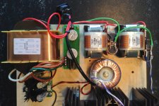
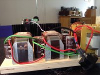
So here are the pictures of my new power supply. It's quite elaborate so I needed to rearrange the complete layout. I put the wave IO on top of the Pi, I still use two streamers, the Alix and the Pi; Alix through Wave IO and Pi I2S connected. I like the Pi more. Just waiting for Russ White to release the cape for the BBB.
On to the supply: on the left side there is a big 200VA transformer (sec. 2x12V), a friend of mine had ordered these specially manufactured to order for use with other Dacs and CD players. This is a really awesome transformer!
It is a simple CLCLC supply using two Silmic 2200uf caps parallel and Lundahl filament chokes.
This supply surpasses all supplies I have used up to date, including the one from Bernd during the visit at Klaus!
It's been a long time since I had so much goose bumps listening to music
Advantages: dynamics, openness, forcefull, detailed, more space, did I mention dynamics?
This one will stay for sure!
The Salas supply is for the Pi and Wave IO.
Regards,
Attachments

It looks very good, and doesn't seem to be very difficult.
On green PCB, is it a diode bridge ?
So to sum up, you're just feeding MB and decks with this >12VDC current, and let the shunt regs do their jobs ?
It sounds easier than feeding 8V and 3.3V with separate external regs...
How much does the chokes cost ?
On green PCB, is it a diode bridge ?
So to sum up, you're just feeding MB and decks with this >12VDC current, and let the shunt regs do their jobs ?
It sounds easier than feeding 8V and 3.3V with separate external regs...
How much does the chokes cost ?
Last edited:
Wow, that's serious tweaking!
Interesting to read your rpi results. What software do you use on it?
I found originally i liked the rpi over i2s, but listening longer i found that some songs had a significant smaller soundstage than my sbt over coax.
I'm using picoreplayer (as this had better volume control and spotify over volumio).
So I have not made any comparisons. Just using comments others have made along with my experience with other circuits.
Whether it is worth the trouble to replace with SILMICs I hope to hear from others, also. Just for reassurance - I am going to use the SILMICs.
I have removed the standard regulators and will replace with the smallest package BELLESONs. Figuring the OS COMs for the digital side and SILMICs for the analogue. Going to use a separate raw supply for digital (3.3) and analogue (8) and not use the shunt supply since Brian Lowe does not recommend the use of a pre-regulator.
A little PCB surgery will be required to separate the 3.3 from 8.
Other than the output caps, are any of the many caps on this project analog? They all seem to be in a regulator position, or on the non output side of the DAC chips.
It looks very good, and doesn't seem to be very difficult.
On green PCB, is it a diode bridge ?
So to sum up, you're just feeding MB and decks with this >12VDC current, and let the shunt regs do their jobs ?
It sounds easier than feeding 8V and 3.3V with separate external regs...
How much does the chokes cost ?
Yes, it's just a replacement for the standard power supply. The shunt does the regulating, the AC ripple is already very low with two chokes so there is really no reason to use extra regulation.
On the Green PCB there are some nice Schottky diodes from Vishay; VS-15TQ060PBF in TO-220 package, and two Silmics.
I did not build separate regs for 3.3v and 8v because I already have the shunts on the dac boards. Shunts are pretty expensive so if you are starting out with a new dac it will be cheaper to build two regulated power supplies. Cannot comment if this will be better than my current setup but it will defenitely be possible to beat the sound of the standard regulators on the boards.
@rovinggecko,
The Pi is running Volumio. I use the volumio volume regulation only when using background music; for serious listening the volume is set on my amps.
I'm going to try the new volumio 1.3beta, it runs with the latest mpd player 0.18.10.
@Bones13,
The output caps are the only ones in the analog signal way (try to get rid of them
). But most of the power supply electroytics are in the analog power supply.
Last edited:
I just updated the circuits and PCB PDFs on my web site. This file is now 100% in line with the new main board and also the power supply and DAC boards are. There were some small revisions, like the 1uF capacitor after the LDO, but also I went back to 100Ohm in the dataline and for the R-L circuits I used 10 Ohm for both. No big things, but now it is all aligned with each other. It is on my download section on the web page or directly here:
dddac1794s_nos_ver42.pdf
dddac1794s_nos_ver42.pdf
I will be using a TVC volume control which will ...
Having Dave Slagle make them.
eliminate any need for output capacitors and allow direct connection to the amplifiers (since there is now a way to control attenuation).Other than the output caps, are any of the many caps on this project analog? They all seem to be in a regulator position, or on the non output side of the DAC chips.
Having Dave Slagle make them.
I do not see an R22 - or a resistor at all in the digital ...
I, too, would much rather use the LUNDAHL chokes. They are expensive here in the US. A future upgrade, certainly. Those supplies look right!
Glad to hear you are having good luck with the shunts. If they sound good they sound good, that is all that matters - but it would be interesting to see how they test.
power supply path on the DAC board. I feel sure you do not mean the 22R R2 resistor which is in the analogue path.Hi Rick,
I wanted to test the dac in its original form before changing the components, that's why the muse is soldered in. This, of course, has its downside
The shunts work very good, they get pretty hot, you can bearly touch them. I have them running for about a year now, my dac is always turned on, and they still work great. They are set at 40 and 35mA, so they waste quite some energy in heat. That, among others, is the reason I have my dac still mounted, open space, on a board.
Splitting the digital power is easiest by letting out r22 and just connect your 3.3v supply on the r22 hole. If you like you can add r22 on your raw power supply.
I finished my new raw power supply today with a very nice 200va transformer and two lundahl chokes. The chokes have been running last week with another trannie and I soldered the big trannie in today.
The shunts on the dac boards do really not need any pre-regulation. It sounds quite a margin better with the new power supply!
I will post a picture soon.
Regards,
I, too, would much rather use the LUNDAHL chokes. They are expensive here in the US. A future upgrade, certainly. Those supplies look right!
Glad to hear you are having good luck with the shunts. If they sound good they sound good, that is all that matters - but it would be interesting to see how they test.
They are not cheap in the Netherlands eitherThey are expensive here in the US. A
Hi,
This supply surpasses all supplies I have used up to date, including the one from Bernd during the visit at Klaus!
It's been a long time since I had so much goose bumps listening to music
Advantages: dynamics, openness, forcefull, detailed, more space, did I mention dynamics?
This one will stay for sure!
Stefan,
congratulations !!!! from the bottom of my heart !!!!
please tell me, when can I have a listen ?
Did not think they were "cheap", but ...
I suspect more than a little less than they are here!
They are not cheap in the Netherlands either
I suspect more than a little less than they are here!
@Bones13,
The output caps are the only ones in the analog signal way (try to get rid of them
I plan on using the Sowter transformers for balanced output when I ever start putting things together.
I do like your unregulated PSU, it seems like I'm hitting my head on the wall to make a regulated PS at 1 amp or even the 1.5 or 2 that might make a difference. Makes sense though that a high quality amp type PSU might be the trick. I was starting to try figuring out the Salas shunts, after getting some boards from Teabag. All the regulated, or shunt regulated PSUs seem to be aimed at 0.4 to just about 1 amp. Then you get nebulous comments like "increase the heatsink" I'm sure there is more to it than that. But then I'm not really an electronics person, just a wanna be with decent math skills, ability to follow direction (or figure it out from pictures, and above average eye/hand coordination.
I happily ordered Doede's power supplies, but I'm always up for tweaking during the build, and I'm finding this thread fascinating.
I currently plan a double chassis unit with the PSUs on top, with the power switch. If I stick with the Salas shunts, I'll be using heat sinks on the sides, shunt on each side. Bottom chassis will have the DAC, and hopefully a BeagleBoneBlack with the Botic cape, it it comes available. I secured the computer already, and understand that you can get I2S out the mini HDMI port if the cape does not make it.
Trying to decide if I can get info for the BBB to display on that chassis, or leave it blank like my current DAC is. Without the Wave I/O board in the loop, the Arduino board does not get the data for display.
Interesting work on the power supplies here guys. We seem to now have two ways forward for powering this dac. Stevan has shown what can be done to get the best out of the shunts, whilst I and a few others are planning on experimenting with larger regulators powering the analogue and digital aspects of the board independently.
Arriving soon at my house are enough super regulators for discrete left / right 3.3v and 8v supply plus another for the mainboard. The biggest question in my mind is: where do I attach the +ve/-ve output of each regulator in order to power those parts of the board individually?
Arriving soon at my house are enough super regulators for discrete left / right 3.3v and 8v supply plus another for the mainboard. The biggest question in my mind is: where do I attach the +ve/-ve output of each regulator in order to power those parts of the board individually?
- Home
- Source & Line
- Digital Line Level
- A NOS 192/24 DAC with the PCM1794 (and WaveIO USB input)