Its the spice JFET models don't care maybe. I have read many times they are not the most elaborate in conception VS BJT models for instance. Thanks for the welcome, I wish I knew how to repair a TV myself. Me just a simple audio circuits hobbyist, messing up all the time.
Its the spice JFET models don't care maybe. I have read many times they are not the most elaborate in conception VS BJT models for instance. Thanks for the welcome, I wish I knew how to repair a TV myself. Me just a simple audio circuits hobbyist, messing up all the time.
You are very humble, typical of those who truly know.
Just seeing your designs can be seen clearly.
BTW, I am designing a 650 V PSU, I hope you don't mind if yours inspire me.

Last edited:
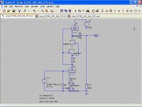
Maybe a J309 for cascode's top? How that fairs in your sim?
Thanks for your advice.
According to the datasheet, the J309 looks good, I must only find the mathematical model.
I must confess that I hate Fairchild's bureaucracy whenever I seek any model.
As I have, I will publish the results.
Last edited:
Hi Salas
I found a model from Philips, thanks a lot, I will try your model soon.
J309 is a very clever choice, distortion remains the same because of +B, but now, noise is lower.
I found a model from Philips, thanks a lot, I will try your model soon.
J309 is a very clever choice, distortion remains the same because of +B, but now, noise is lower.
Attachments

Johan, did you ever build this setup?
No, I didn't, because it is a thought experiment, and here is impossible to obtain good JFETs, only fakes.
However I did the normal SRPP, without JFETs, and it sounds amazingly transparent, no need sand after all.
What about exchanging a 25Kohm pot for R11?
Not the best place to put a pot, because of output impedance and frequency roll off, a better place should be at the input, before R5. IMHO
Would the extra capacitance (because of the pot) lower residual noise even more?
I don't understand what do you mean, but, the best solution I found regarding noise, frequency response and phase shift is
Low gain SRPP => 100K pot => SLCF
Same approach here
http://www.diyaudio.com/forums/tubes-valves/228331-volume-pot-hidden-villain-preamp.html
Dear Popilin, How are you my dearest friend?
Hy Dady
I'm a bit busy, last night, I was until 3:00 AM reneging with an old big TV, a very tricky failure, with a very tricky solution because of a damn unobtainable hybrid chip, I must do it by myself.
My job sucks, no solution, no money...
The SRPP can be optimized for a constant load. Why not use a low value pot for (most part of) this load? More so as the noise contribution of a pot will be less with the least gain after it.Not the best place to put a pot, because of output impedance and frequency roll off, a better place should be at the input, before R5. IMHOCode:Originally Posted by disco; What about exchanging a 25Kohm pot for R11?
popilin said:I don't understand what do you mean, but, the best solution I found regarding noise, frequency response and phase shift is
Low gain SRPP => 100K pot => SLCF
I was thinking about limiting the pre bandwith. But than again the low pass filter would influence phase shift..
There was good information, thanks all for sharing.popilin said:
* to use the lowest resistance pot possible as a large value pot contributes more noise than a smaller value one;
* restrict the change of bandwith of the circuit as it can vary a lot depending on pot position;
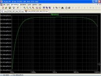
* to keep amplitude response [20-20K] within +/- 0.1dB by extending the lower and upper cut-off by a decade;
* to choose the optimal ECC82 tube current as a trade-off between tube current and noise;
Increased tube current can reduce noise but brings bias closer to zero, which increases grid leakage current, increasing noise.
At audio frequencies flicker noise is at least as important (as shot noise) and gets less as Ia is reduced, the exact opposite of shot noise.
The SRPP can be optimized for a constant load. Why not use a low value pot for (most part of) this load? More so as the noise contribution of a pot will be less with the least gain after it.
I was thinking about limiting the pre bandwith. But than again the low pass filter would influence phase shift..
There was good information, thanks all for sharing.
* to use the lowest resistance pot possible as a large value pot contributes more noise than a smaller value one;
* restrict the change of bandwith of the circuit as it can vary a lot depending on pot position;
* to keep amplitude response [20-20K] within +/- 0.1dB by extending the lower and upper cut-off by a decade;
* to choose the optimal ECC82 tube current as a trade-off between tube current and noise;
Increased tube current can reduce noise but brings bias closer to zero, which increases grid leakage current, increasing noise.
At audio frequencies flicker noise is at least as important (as shot noise) and gets less as Ia is reduced, the exact opposite of shot noise.
Because of dielectric anisotropy, the constitutive relation
D = ε E
Needs that ε must be a tensor, and the curve D=f(E) is called dielectric hysteresis curve, then, in order to preserve linearity we must avoid the use of enormous capacitors, so a 100 K volume pot is a good compromise between noise and capacitor size.
Even so, the ECC82 noise density is about same order of magnitude than of the 100 K pot, so with proposed scheme, don't worry about current (noise), you can easily concern only about distortion.
Last edited:
Because of dielectric anisotropy, the constitutive relation
D = ε E
Needs that ε must be a tensor, and the curve D=f(E) is called dielectric hysteresis curve, then, in order to preserve linearity we must avoid the use of enormous capacitors, so a 100 K volume pot is a good compromise between noise and capacitor size.
Even so, the ECC82 noise density is about same order of magnitude than of the 100 K pot, so with proposed scheme, don't worry about current (noise), you can easily concern only about distortion.
Ok, after some study I now have a little understanding of tensors
Had a couple of octals waiting for employment so I build a small SRPP setup:
An externally hosted image should be here but it was not working when we last tested it.
The output is taken from the wiper of R6
It's loaded by the quite low R5||R6 resistance but I measured circa 0.2 volt DC over C1.
Is this DC offset caused by the effect you're hinting at in the above post?
Last edited:
Ok, after some study I now have a little understanding of tensorsNeeds that ε must be a tensor, and the curve D=f(E) is called dielectric hysteresis curve, then, in order to preserve linearity we must avoid the use of enormous capacitors, so a 100 K volume pot is a good compromise between noise and capacitor size.
Popilin loves quoting that, but it's totally misguided. In a given circuit, using a bigger capacitor will result in less distortion, not more, because the signal voltage across the cap will be reduced. The exact opposite of what he implies.
That's what I red in the parallel thread, it's an AC property, not?
Merlin, wrt my spontanous outburst of creativity, does the top resistor affect 2H?
Did I remember right that SRPP cancels distortion from equal but opposite AC conditions for both triodes?
It sounds pretty euphoric
Merlin, wrt my spontanous outburst of creativity, does the top resistor affect 2H?
Did I remember right that SRPP cancels distortion from equal but opposite AC conditions for both triodes?
It sounds pretty euphoric
The optimum load for an SRPP is often significantly lower than the output impedance, so gain goes down. OK if this is what you want.disco said:The SRPP can be optimized for a constant load. Why not use a low value pot for (most part of) this load?
Yes, just like push-pull. To get this you need a balanced circuit (not all 'SRPP' are properly balanced), and either high impedance load or the optimum load.Did I remember right that SRPP cancels distortion from equal but opposite AC conditions for both triodes?
Mixing up tensors (anisotropy) and dielectric hysteresis is unhelpful as they relate to quite different effects. Anisotropy, where present, may be an issue for capacitor designers but it has no relevance for capacitor users.
Ok, after some study I now have a little understanding of tensors
Had a couple of octals waiting for employment so I build a small SRPP setup:
An externally hosted image should be here but it was not working when we last tested it.
The output is taken from the wiper of R6
It's loaded by the quite low R5||R6 resistance but I measured circa 0.2 volt DC over C1.
Is this DC offset caused by the effect you're hinting at in the above post?
No, I don't think so, one extreme of C1 is at about +B/2 and the other extreme is grounded by R5||R6, then your DC offset probably is caused by a low frequency oscillation and/or your instrument, especially if it is a DVM. IMHO
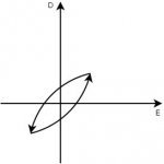
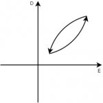
To understand what I mean without using tensors, you must suffer my drawings.
On a coupling cap without DC bias, the dielectric must be polarized cycle by cycle, so the electric field E changes its sign and consequently its sense of direction, this means zero crossing.
On a coupling cap with enough DC bias, the dielectric is already polarized, so the electric field E doesn't changes its sign and consequently doesn't changes its sense of direction, this means no zero crossing.
Can be proven that for two conducting parallel plates, filled with a dielectric of "constant" ε, capacitance is
C = (ε A) / (4πd)
Where
ε = Dielectric constant [cgs] dimensionless
A = Plate area [cm²]
d = Dielectric thickness [cm]
[C] = cm, 1cm ≈ 1.113 pF
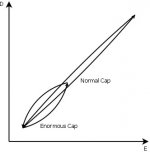
For a given dielectric (ε), to increase capacitance, because d is already decreased/optimized, so you must increase A, so you must increase the volume of the dielectric, then dielectric hysteresis losses increases, then the area inside the loop is bigger and this way you can destroy linearity.
The decrease on applied signal voltage varies linearly with capacitance, but losses doesn't, actually them varies exponentially with the volume of the dielectric, then exists a theoretical limit beyond that bigger is not better.
Some people can't understand this because they believe that capacitors are ideal devices, sorry to say that, but, real world capacitors do have losses.
Let's suppose now that we use a normal capacitor, and following the advice that it is said out there, we decide to replace it by an enormous capacitor, and being generous let's suppose also that both capacitors has same losses, i.e. same area inside the hysteresis loop.
Clearly the normal capacitor is more linear by far, even when the signal voltage across the enormous cap has been reduced.
Engineers has a different approach, making a great simplification, ignoring dielectric anisotropy, can consider
ε = ε' + i ε"
Then, dielectric loss
P = Po exp (- δ k z)
Where
tan (δ) = ε" / ε'
They refer losses as "dielectric absorption", related with tan (δ).
Also, capacitor manufacturers in their datasheets, exhibits the best properties, i.e. lowest tan (δ), at about 100 nF
http://www.google.com.ar/url?sa=t&rct=j&q=&esrc=s&source=web&cd=3&ved=0CD8QFjAC&url=http%3A%2F%2Felektrotanya.com%2Ffiles%2Fforum%2F2014%2F04%2FX2_B81130.pdf&ei=EadrU7m2MIX2oASYuoKoCg&usg=AFQjCNEcJPcXVSH1ZJaLQmtlNCB03K456Q&bvm=bv.66330100,d.cGU&cad=rja
Morgan Jones on his book "Valve Amplifiers" has an entire chapter about capacitors.
Ah, by the way, he also encourage that don't using capacitors too big.
Attachments
Last edited:
Mixing up tensors (anisotropy) and dielectric hysteresis is unhelpful as they relate to quite different effects.
As a physicist, you MUST KNOW that hysteresis is a consequence of anisotropy.
On an homogeneous and isotropic medium, the constitutive relations
D = ε E
B = μ H
Are LINEAR, so NO hysteresis. AFAIK
B = μ H
Are LINEAR, so NO hysteresis. AFAIK
- Status
- This old topic is closed. If you want to reopen this topic, contact a moderator using the "Report Post" button.
- Home
- Member Areas
- The Lounge
- ECC82/12AU7 Line Preamp