"The only thing I could think of is if the reinforcement current is sufficient to induct voltage into the ground loop. If one were to use two independent AC circuits to power a system and the system loop includes the grounds to panel, then that could really play whoopie with noise."
JN,
In a typical older house here in California where we still used metallic flex conduit I have never seen more than one actual ground connection that would be located at the distribution panel. All of this conduit would be connected back to the box with that being the sole ground connection to earth and this flex would be used as the ground connection, no third wire ground connections used. If you used a multi-connection three pronged wall socket with two outlets where would you develop a ground loop outside of the loop you would just create by using multiple power cords? Do you really need to consider the small loop you could possibly have in the single ground source through the conduit or is the real problem coming on the outside of this connection through ground loops in the power cords and any cabling required between audio sources. I am leaving out any ground loops that would come from the external ground plane caused by multiple grounds that the power company uses to ground the high tension wires and the multiple transformers as I don't see how you can isolate this before the wall outlet.
This of course would be a highly different situation with the current use of Romex and the fact that that uses three wires, one power, one neutral and one ground wire all running in parallel the entire length of wire, I would think this a much worse situation than the wire in conduit though the wire in conduit is also basically parallel pairs with little to no twist though you could pull a particular section and run a twisted pair if you could pull it down the conduit.
The only thing I could think of is if the reinforcement current is sufficient to induct voltage into the ground loop. If one were to use two independent AC circuits to power a system and the system loop includes the grounds to panel, then that could really play whoopie with noise.
jn
Related: I just spend a few hours trying to remove the hf junk spewed back from my PC into the mains that feeds the rest of the test equipment. I did have more than a mV hash on a shorted scope input.
In the end I ended up using two mains filters in series, both on the PC as well as on the rest of the lab stuff.
Interestingly (for me), if I connected the PE from the mains to the 1st filter input PE, to the 2nd filter input PE, then to the load side PE, it didn't work as well as by a large margin, than when I just connected the PE to the 1st filter and the load only, bypassing the PE input pin of the 2nd filter.
Jan
If you used a multi-connection three pronged wall socket with two outlets where would you develop a ground loop outside of the loop you would just create by using multiple power cords?
I wasn't considering bx, flex conduit, or rigid conduit. Perhaps I should have chosen my words more carefully and said powered by two branch circuits of romex, or two branches of independent semirigid..
I was only speaking about two independent 3 wire branches. The safety bonding conductor of two branches tie only back at the distribution panel, so an amp in one and a sub in another will take the loop to the panel.Do you really need to consider the small loop you could possibly have in the single ground source through the conduit or is the real problem coming on the outside of this connection through ground loops in the power cords and any cabling required between audio sources.
If a two pronger and a three pronger share a semirigid to the panel, the amp uses the semirigid, but the two pronger has a neutral in a tube with a hot all the way back. I think there could be issues there.
I am leaving out any ground loops that would come from the external ground plane caused by multiple grounds that the power company uses to ground the high tension wires and the multiple transformers as I don't see how you can isolate this before the wall outlet.
As long as the house is earthed at one point, and bonded there as well, then the only issue left would be cable entrances that are not bonded at the service entrance.
Whitlock has started considering the multiple wire conduit scenario in that big 2012 presentation. He also mentioned twisting the hots/neutrals and not twisting the bonding conductor to prevent transformer action in the conduit.This of course would be a highly different situation with the current use of Romex and the fact that that uses three wires, one power, one neutral and one ground wire all running in parallel the entire length of wire, I would think this a much worse situation than the wire in conduit though the wire in conduit is also basically parallel pairs with little to no twist though you could pull a particular section and run a twisted pair if you could pull it down the conduit.
jn
JN, it would be nice if you provided members here with your suggestion and drawing of practical interconnection of home audio systems with respect to signal and power cables, all optimized to minimum EMI and RFI pickup. What do you think.

http://www.diyaudio.com/forums/gallery/showphoto.php/photo/9533
jn
Thanks for sharing jn. I'll need to read through carefully to digest fully.
I am approaching the problem differently (but possibly incorrectly) with seemingly reasonable results.
I use headphones directly connected to the speaker output of the amp. With no input on the power amp the hum is ZERO. When I attach the pre, I get very low level hum (not audible on the speakers, but with phones you can hear it).
I'll lpost up the wiring config a bit later - might generate some good discussion and insights.
Last edited:
jn, if you run two twisted pairs together along a path, where one might be an aggressor, what would be the optimum twisting and laying strategy to minimise any coupling: differing levels of twist, opposing twists, twisting of the two pairs with respect to each other, etc, ... ?Even then, a twisted pair is NOT impervious to nearfield magnetic induction. It cancels if two consecutive loops trap the same thing. If an odd number of loops trap, there will be induction. If it is near an agressor with the same twist pitch, there will be coupling
jn, if you run two twisted pairs together along a path, where one might be an aggressor, what would be the optimum twisting and laying strategy to minimise any coupling: differing levels of twist, opposing twists, twisting of the two pairs with respect to each other, etc, ... ?
Its called CAT5, CAT6, CAT7 networking cable. The story is that AT&T used a big computer to calculate the optimum twist ratio and it took weeks of CPU time. I'm not sure I completely buy the story but the turns ratios on the 4 pair are very specific and tightly controlled to meet the crosstalk specs in the EIA-TIA standards. The certified cables are all verified on a network analyzer for all the performance parameters. However you can buy a $1500+ ethernet cable: AudioQuest Ethernet Cables | AudioStream Amazon.com: 1.5m (5') Audioquest Diamond RJ/E (Ethernet) Cable: Computers & Accessories Ethernet Diamond but I see no evidence that it has even been tested.
The real world of CAT is a bit messy - see here, Is Your Cat 6 Cable a Dog? -- Blue Jeans Cable - and number of twists is treated as IP it seems; either buy the document specifying everything, or buy a good quality sample of the stuff and pull it apart ...
> We actually paid serious money to have Carlos speak at MIT ~1970
He was cited over and over in early popular ' intros to quantum physics '
I.E......." The Tao of Physics " ( Formative for Me )
http://en.wikipedia.org/wiki/The_Tao_of_Physics
He was cited over and over in early popular ' intros to quantum physics '
I.E......." The Tao of Physics " ( Formative for Me
)http://en.wikipedia.org/wiki/The_Tao_of_Physics
Last edited:
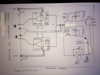
Attached is how I am doing it at the moment. The 'T' is about 1" end to end length
Attachments
Last edited:
I should add:-
I twist the amp module ground return and supply rails together (I never used to do that)
I keep the speaker return and the +ve twisted for about 1/3 or the length, but then about 2/3rd is not twisted as it is returned to the 'T'
The input cabling is kept well away from other wiring
All transformer secondary's are twisted up to the rectifiers
Mains L and N twisted together
Secondaries and primary wiring kept well away from other cabling.
Only 1 earth bond point on the chassis (located close to IEC inlet)
I have not fitted the input phono socket signal return (i.e. signal GND) to chassis capacitors - I need to do that.
Attached is how I am doing it at the moment. The 'T' is about 1" end to end length
You inserted 15 ohms in series with your signal grounds?? Then cross-couple the grounds through capacitors to the chassis, then have a chassis path through 22 ohms to the electrical GND T. I’ve seen similar configurations used to enhance the L – R element of a stereo signal, though at these values I’m not sure that would have an audible effect in this case, especially if the grounds are common at the source.
jn, if you run two twisted pairs together along a path, where one might be an aggressor, what would be the optimum twisting and laying strategy to minimise any coupling: differing levels of twist, opposing twists, twisting of the two pairs with respect to each other, etc, ... ?
Common mode noise rejection.
JNs stuff has the mains cables in close proximity to the ICs to minimise the loop area, slightly different problems.
The real world of CAT is a bit messy - see here, Is Your Cat 6 Cable a Dog? -- Blue Jeans Cable - and number of twists is treated as IP it seems; either buy the document specifying everything, or buy a good quality sample of the stuff and pull it apart ...
Not really....don't believe everything you read in an audio cable company,s comments, use a well know supplier. Its not exactly uncommon is cat5-7.
You inserted 15 ohms in series with your signal grounds?? Then cross-couple the grounds through capacitors to the chassis, then have a chassis path through 22 ohms to the electrical GND T. I’ve seen similar configurations used to enhance the L – R element of a stereo signal, though at these values I’m not sure that would have an audible effect in this case, especially if the grounds are common at the source.
The caps (some use lower e.g. 100-200pF) are to connect the shield to the chassis at RF - They have no effect at audio. There is no signal conduction through the chassis at audio.
You can also run an earth connection from the PCB GND back to the star ground (with the 15 Ohm signal ground isolation R in situ), but I do not note any improvement doing this (this method is shown in some texts - with and without the signal GND iso R)
Its called CAT5, CAT6, CAT7 networking cable. The story is that AT&T used a big computer to calculate the optimum twist ratio and it took weeks of CPU time. I'm not sure I completely buy the story but the turns ratios on the 4 pair are very specific and tightly controlled to meet the crosstalk specs in the EIA-TIA standards. The certified cables are all verified on a network analyzer for all the performance parameters. However you can buy a $1500+ ethernet cable: AudioQuest Ethernet Cables | AudioStream Amazon.com: 1.5m (5') Audioquest Diamond RJ/E (Ethernet) Cable: Computers & Accessories Ethernet Diamond but I see no evidence that it has even been tested.
That cable should be in the snake oil thread.
Wot a joke.The caps (some use lower e.g. 100-200pF) are to connect the shield to the chassis at RF - They have no effect at audio. There is no signal conduction through the chassis at audio.
You can also run an earth connection from the PCB GND back to the star ground (with the 15 Ohm signal ground isolation R in situ), but I do not note any improvement doing this (this method is shown in some texts - with and without the signal GND iso R)
At the values that you’re using I certainly wouldn’t expect any effect at audio frequencies. It was more just a theoretical observation/comment about the configuration and the potential for a different amplifier gain for L + R vs a L – R signal aspect between the two channels; - that is if larger component values were used such that it did cut down into the audio band, and were roughly on the scale of the amplifier’s inverting input’s Rs. The caveat being that the two grounds would need to be isolated from one another at the source (dual mono pre with Transformer inputs). Sorry, I realize this is a lateral from your focus on noise minimization. Probably shouldn’t have even bothered to mention it.
- Status
- Not open for further replies.
- Home
- Member Areas
- The Lounge
- John Curl's Blowtorch preamplifier part II