Demian, do you know if 1616m head is compatible with 1010 from 1212m set?
I am thinking to buy 1616m head because of its mic preamps. Will it work?
Lets take this here: http://www.diyaudio.com/forums/equipment-tools/248720-emu-1212m-measurements-6.html#post3917862 since its more relevant in the discussion of the EMU stuff there.
Ha! Just bought 1212m PCI on ebay! 200CAD with shipping.
Yes, I've found Vout of my preamp was ~140V after I've measured it during touching grid of input tube to make that buzz that destroyed my 0404.
After that I've put two 2.7V (could not find lower) zenners back-to back to its out, and two bright red LEDs between them so they indicate overload.
I think this will allow not more than 7Vp-p.
What diodes would you recommend?
The usual practice is to create the voltage limits (usually the power supplies) and clamp with reverse biased 1n4148 diodes. That works well and is low distortion but you need the supplies and a series resistance to limit the current. Using Zeners introduces distortion because they start conducting well below the clamp voltage. Doing this in a tube system is difficult since there are no low voltage supplies to make use of.
What is the output impedance of the tube circuit?
I do not know Zout, did not measured it. It should be low, 150R or less.
the current schematic is here: http://www.diyaudio.com/forums/tubes-valves/234937-ribbon-microphone-preamp-65.html#post3899733
Could you please advice a protection with less distortion?
the current schematic is here: http://www.diyaudio.com/forums/tubes-valves/234937-ribbon-microphone-preamp-65.html#post3899733
Could you please advice a protection with less distortion?
With the low output impedance you can get enough current to damage devices.
The best way to protect would be the following-
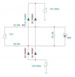
create a +&- supply at the voltage limits you need -.7V (if possible). Connect reverse biased diodes from each rail to the input. The diodes won't conduct until the input swigs past the voltage rail. You need some form of additional protection however. The options are a fuse (100 mA), a series resistor that can handle the worst case voltage and current (10K 2W?) or a miniature lightbulb rated for the max voltage. The lightbulb is attractive because when cold, normal case, its resistance is low but when power is applied its resistance increases limiting the current as it warms up. This is what I see in current generation distortion analyzers.
The best way to protect would be the following-
create a +&- supply at the voltage limits you need -.7V (if possible). Connect reverse biased diodes from each rail to the input. The diodes won't conduct until the input swigs past the voltage rail. You need some form of additional protection however. The options are a fuse (100 mA), a series resistor that can handle the worst case voltage and current (10K 2W?) or a miniature lightbulb rated for the max voltage. The lightbulb is attractive because when cold, normal case, its resistance is low but when power is applied its resistance increases limiting the current as it warms up. This is what I see in current generation distortion analyzers.
Thanks Demian. I tried it in Tina TI SPICE. With Vs +- 500m and Vin 150V it decreases Vout down to +-2.5V, which is still kind of overvoltage, though I suppose it is tolerable by most of line inputs.
In LTSpice it behaves weirdly, it reduces Vout to +-35V.
In LTSpice it behaves weirdly, it reduces Vout to +-35V.
Attachments
Hello friends.
What is your opinion about ADC:
1) What Fs is enough and what "nice to have"?
2) If ADC dedicated to the measurements only, should it be stereo, or it can be mono?
3) Is SE Input is enough, or it must be differential?
4) What the input sensitivity is preferable? I mean what is tha maximim input voltage, 0dBFS ?
Thank you.
Lets move it to my question threadMuch too big a diode. Try it with 1N914 or 1N4148. The capacitance of the big diode will degrade everything.
The voltages to clamp to are the supply rails of the input opamp. Most semis can handle as much at .7V beyond the rails on their inputs without damage.
http://www.diyaudio.com/forums/tubes-valves/254674-protection-downstream-line-amp.html#post3920132
Hello friends.
What is your opinion about ADC:
1) What Fs is enough and what "nice to have"?
2) If ADC dedicated to the measurements only, should it be stereo, or it can be mono?
3) Is SE Input is enough, or it must be differential?
4) What the input sensitivity is preferable? I mean what is tha maximim input voltage, 0dBFS ?
Thank you.
There are several efforts around DIYaudio to do exactly this. I know Jens' is in the final troubleshooting stages and looks very promising at this point. http://www.diyaudio.com/forums/equipment-tools/245852-buffers-adc-design-ak5394a-other-adcs.html
The answers to your questions are not simple. I was using an approach driven by what the device to be measured needs and a lot of the level matching etc. would be in the cabling. This explains better http://www.diyaudio.com/forums/equipment-tools/231401-quantasylum-qa400.html#post3396418 I think the need for differential in and active balanced/unbalanced out is critical. Especially if a computer is in the mix.
In commercially available ADC's nothing I have measured comes close to the AK5394A. AKM has a note on bonding two channels to get a lower noise floor. I'm not sure there is any distortion benefit. The AKM shows no performance degradation I have found at 192KHz sampling over 96 or 48.
For DAC's for measurement purposes the ESS is the best. I don't know why I don't like the sound but that's a different aspect.
In detail:
1) What Fs is enough and what "nice to have"? 192KHz and 48KHz for compatibility with existing software.
2) If ADC dedicated to the measurements only, should it be stereo, or it can be mono? Stereo for compatibility and ease of use.
3) Is SE Input is enough, or it must be differential? Differential is really a requirement to keep the ground noises out.
4) What the input sensitivity is preferable? I mean what is the maximum input voltage, 0dBFS ? I think 3V would be ideal- compatible with most commercial line level signalling. Use a seperate preamp/signal conditioner for lower level signals and an external probe-cable with attenuation for high level signals.
Hi Demian, thanks for the reply.
It is not clear to me - does anybody have ADC and preamplifier, that can be used for small THD measurements without the notch-filter?
All my efforts this time: 2nd-3rd harmonics are ~ -115-120dBFS @ 0dB signal, with some schematic limitations (SE Input, single polarity power supply).
I agree that more then 192 is not usefull now due to a SW, but what the sense of 48?
It is not big difference between 48 and 96 in point of SNR/THD.
192 have a problem with PC Input - it requires UAC2, that is good for Mac/Lin users, but Win require external driver. So, it is not for DIYr-s.
I have spend a years with SpectraLab/SpectraPlus, and except the speaker measurement (internal sound card is more then enough, or something like the simple PCM29xx based "$3 device from EBay"), where on channel is a reference for another and the "Transfer Function" is viewed on Spectrum Analyser, I don't remember when I need 2 channels.
Why a I asked this question - we all know, that ADC has it's own THD at high level. Using ADC chip 2 channels together can be implemented in 2 ways with the different results:
1) using each channel full scale with averaging, we will get SNR 3dB better.
2) the same, but each channel input signal is -3dBFS limited. We will get the same SNR as at the regular use, but less ADC's harmonics, at the close to 0dBFS area (summary!).
Also ADC chip Input over voltage protection will be more far away from the real operating voltages.
Of course, it is possible to make the same in 2 channels, it is only the question of the price (2 ADC chips).
But most of the signal sources (DUT ) are SE.
I read this thread.There are several efforts around DIYaudio to do exactly this. I know Jens' is in the final troubleshooting stages and looks very promising at this point. http://www.diyaudio.com/forums/equipment-tools/245852-buffers-adc-design-ak5394a-other-adcs.html
It is not clear to me - does anybody have ADC and preamplifier, that can be used for small THD measurements without the notch-filter?
All my efforts this time: 2nd-3rd harmonics are ~ -115-120dBFS @ 0dB signal, with some schematic limitations (SE Input, single polarity power supply).
In detail:
1) What Fs is enough and what "nice to have"? 192KHz and 48KHz for compatibility with existing software.
I agree that more then 192 is not usefull now due to a SW, but what the sense of 48?
It is not big difference between 48 and 96 in point of SNR/THD.
192 have a problem with PC Input - it requires UAC2, that is good for Mac/Lin users, but Win require external driver. So, it is not for DIYr-s.
2) If ADC dedicated to the measurements only, should it be stereo, or it can be mono? Stereo for compatibility and ease of use.
I have spend a years with SpectraLab/SpectraPlus, and except the speaker measurement (internal sound card is more then enough, or something like the simple PCM29xx based "$3 device from EBay"), where on channel is a reference for another and the "Transfer Function" is viewed on Spectrum Analyser, I don't remember when I need 2 channels.
Why a I asked this question - we all know, that ADC has it's own THD at high level. Using ADC chip 2 channels together can be implemented in 2 ways with the different results:
1) using each channel full scale with averaging, we will get SNR 3dB better.
2) the same, but each channel input signal is -3dBFS limited. We will get the same SNR as at the regular use, but less ADC's harmonics, at the close to 0dBFS area (summary!).
Also ADC chip Input over voltage protection will be more far away from the real operating voltages.
Of course, it is possible to make the same in 2 channels, it is only the question of the price (2 ADC chips).
3) Is SE Input is enough, or it must be differential? Differential is really a requirement to keep the ground noises out.
But most of the signal sources (DUT ) are SE.
One of my ADC (PCM4202) have SE 1V FS input and 20K potentiometer at one channel the input ( Dact Type 21 Stepped Attenuator Volume 20K for Preamp | eBay ), the second channel is direct. I do not see the difference between the channels.4) What the input sensitivity is preferable? I mean what is the maximum input voltage, 0dBFS ? I think 3V would be ideal- compatible with most commercial line level signalling. Use a separate preamp/signal conditioner for lower level signals and an external probe-cable with attenuation for high level signals.
Alex:
Let me add to my short notes.
First, stereo. The existing software for the most part has been written for a stereo source and I'm not sure how it would react to a mono source. it would still expect to see two channels in the PCM stream. The software I use the most, Praxis, needs two channels for most of its acoustic analysis.
I am connecting you with the author of the note on adding two channels to make one. It does require a DSP that runs at 192 to get the full benefit. There is a nice Analog Devices DSP that can do the mixing or you could program an FPGA to do it. What would be interesting is a switchable mode that parallels the two channels for lower noise (maybe lower distortion) when one channel is enough.
When looking at really low noise and low harmonics the analog chain needs to be optimized for the specific source. Usually that means low impedances at the feedback nodes for low noise. 3 volts works fine with line level devices. The standard full scale output of a DAC is 2V RMS. Attenuating it without either raising the noise floor or loading the device requires a selectable gain amplifier. You do not want to be too close to full scale on the ADC or the distortion increases or too low and the SNR decreases. Typically I see about a 10-15 dB range from -3 to -20 as usable.
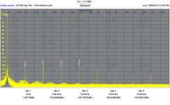
Distortion: The very best I have seen from an ADC is harmonics max around -120 dB. And that from the AK5394A in an optimum setup. (attached) To get lower you need an external analog filter.
At these levels I find I need separate ground connections or the ground currents will really pollute the signal. -120 dB from 1 volt is 1 uV and your trying to look 20 dB below that for noise. Anything that removes the junk is worth the effort. This and dealing with balanced circuits is what I would go the differential route.
Using a USB interface to a computer for measurements causes no end of noise problems. You would need a really good isolator which is not currently possible for USB. Meanwhile transformers for SPDIF/AES work great and with a good source the jitter is not an issue.
48KHz sampling allows comparisons and calibrations (particularly with Praxis, but other applications as well I suspect).
Let me add to my short notes.
First, stereo. The existing software for the most part has been written for a stereo source and I'm not sure how it would react to a mono source. it would still expect to see two channels in the PCM stream. The software I use the most, Praxis, needs two channels for most of its acoustic analysis.
I am connecting you with the author of the note on adding two channels to make one. It does require a DSP that runs at 192 to get the full benefit. There is a nice Analog Devices DSP that can do the mixing or you could program an FPGA to do it. What would be interesting is a switchable mode that parallels the two channels for lower noise (maybe lower distortion) when one channel is enough.
When looking at really low noise and low harmonics the analog chain needs to be optimized for the specific source. Usually that means low impedances at the feedback nodes for low noise. 3 volts works fine with line level devices. The standard full scale output of a DAC is 2V RMS. Attenuating it without either raising the noise floor or loading the device requires a selectable gain amplifier. You do not want to be too close to full scale on the ADC or the distortion increases or too low and the SNR decreases. Typically I see about a 10-15 dB range from -3 to -20 as usable.
Distortion: The very best I have seen from an ADC is harmonics max around -120 dB. And that from the AK5394A in an optimum setup. (attached) To get lower you need an external analog filter.
At these levels I find I need separate ground connections or the ground currents will really pollute the signal. -120 dB from 1 volt is 1 uV and your trying to look 20 dB below that for noise. Anything that removes the junk is worth the effort. This and dealing with balanced circuits is what I would go the differential route.
Using a USB interface to a computer for measurements causes no end of noise problems. You would need a really good isolator which is not currently possible for USB. Meanwhile transformers for SPDIF/AES work great and with a good source the jitter is not an issue.
48KHz sampling allows comparisons and calibrations (particularly with Praxis, but other applications as well I suspect).
Attachments
Demian, could you not solve the USB issues, at the expense of HS operation, with a plastic box containing an ADUM4160 & ADUM5000 in the middle of the devices?
It seems that isolating I2S after the receiver / MCU is a good idea also and would allow 192 KHz operation. The problem I have with this approach is that if you make a device with a metal chassis, you have no choice but to connect the USB shell/shield to the chassis, which may defeat the galvanic isolation.
It seems that isolating I2S after the receiver / MCU is a good idea also and would allow 192 KHz operation. The problem I have with this approach is that if you make a device with a metal chassis, you have no choice but to connect the USB shell/shield to the chassis, which may defeat the galvanic isolation.
Hello Demian,
thank you (ad Joel) for the file, will read it later.
What I'm doing now with mono-ADC - I send stereo, but L and R channels are equal. So, I send the standard signal and every software should work.
In Spectra it is possible to view or both channels, or Left only, or Right only.
I do not use galvanic isolation at USB level, because it is not good, it is expansive and work at UAC1 only (USB LS and FS).
For UAC2 (USB HS) - this time there are now isolation solution at USB level.
I still use UAC1 at 96/24 format, but want to go to UUAC2 in the future device.
Instead of this - I use isolation at I2S level, between ADC and USB-controller (clock is at ADC side, also ADC is a "I2S master", so isolator's jitter does not important).
Power - maybe I will use DC/DC from USB in the future, but now I use 6V 4.5AH battery.
About the input level -most input buffers has the gain ~1/3.
So, why not to set the buffer's gain =1, and (if need) - attenuate the signal on it's input?
thank you (ad Joel) for the file, will read it later.
Alex:
Let me add to my short notes.
First, stereo. The existing software for the most part has been written for a stereo source and I'm not sure how it would react to a mono source. it would still expect to see two channels in the PCM stream. The software I use the most, Praxis, needs two channels for most of its acoustic analysis.
What I'm doing now with mono-ADC - I send stereo, but L and R channels are equal. So, I send the standard signal and every software should work.
In Spectra it is possible to view or both channels, or Left only, or Right only.
I do not use galvanic isolation at USB level, because it is not good, it is expansive and work at UAC1 only (USB LS and FS).
For UAC2 (USB HS) - this time there are now isolation solution at USB level.
I still use UAC1 at 96/24 format, but want to go to UUAC2 in the future device.
Instead of this - I use isolation at I2S level, between ADC and USB-controller (clock is at ADC side, also ADC is a "I2S master", so isolator's jitter does not important).
Power - maybe I will use DC/DC from USB in the future, but now I use 6V 4.5AH battery.
About the input level -most input buffers has the gain ~1/3.
So, why not to set the buffer's gain =1, and (if need) - attenuate the signal on it's input?
Hi Frex,
This post's been a little dead but i found while searching for ADC ideas and I must say I'm impressed, only problem I have is the programed logic array, seen has I didn't want to get involved in to complicated stuff and wanted to make it full diy. I really would be thankfull for another alternative, or program files (if that's possible).
This post's been a little dead but i found while searching for ADC ideas and I must say I'm impressed, only problem I have is the programed logic array, seen has I didn't want to get involved in to complicated stuff and wanted to make it full diy. I really would be thankfull for another alternative, or program files (if that's possible).
Hello Asurans,
Logic array is really easy to program...")
Just need a 10$ USB Blaster from Ebay (or others).
I think to have few bare PCB of this design.
If you are interested to build it or mod it, i can sale you a bare PCB alone
or with the CPLD fully soldered and programmed. So, no big concern to build it !
A very complete design folder with all design and programming files is send to all PCB buyers.
Regards.
Frex
Logic array is really easy to program...
Just need a 10$ USB Blaster from Ebay (or others).
I think to have few bare PCB of this design.
If you are interested to build it or mod it, i can sale you a bare PCB alone
or with the CPLD fully soldered and programmed. So, no big concern to build it !
A very complete design folder with all design and programming files is send to all PCB buyers.
Regards.
Frex
Frex.
I can't find the zip file for the oscillator
http://www.diyaudio.com/forums/equi...ct-audio-measurements-tool-5.html#post2171291
Is there any chance you still have the build information?
Can you send that to my Email again?
I can't find the zip file for the oscillator
http://www.diyaudio.com/forums/equi...ct-audio-measurements-tool-5.html#post2171291
Is there any chance you still have the build information?
Can you send that to my Email again?


- Status
- This old topic is closed. If you want to reopen this topic, contact a moderator using the "Report Post" button.
- Home
- Design & Build
- Equipment & Tools
- DIY Analog-to-Digital Converter project.Audio measurements tool