I have just begun building a DCB1 and have a question. Regarding the soldering of the 1R resistors that have one pole in proximity to the K170 transistors, does the 1R solder need to remain separate from the solder pad of the K170 transistors or can a small amount of solder flow on to the K170 pad. Your well done photos reveal a small gap between the two pads( The 1R and the K170). If this gap is spanned by a small amount of solder do I have a problem that will need correction before proceeding further with the build? Thank for you help.
P.S. This question applies to both sides of the PCB.
Mark
P.S. This question applies to both sides of the PCB.
Mark
ScarF
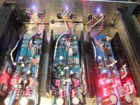
It is not "real" cooling profiles, but L aluminum profiles taken from "slaughtered" KEF 100 Theather System. They are 4 mm thick, and I have no problem with 200 mA. No problems to increase to a higher value, I think. A listening test will desire.
Eivind Stillingen
It is not "real" cooling profiles, but L aluminum profiles taken from "slaughtered" KEF 100 Theather System. They are 4 mm thick, and I have no problem with 200 mA. No problems to increase to a higher value, I think. A listening test will desire.
Eivind Stillingen
You mean the original black single sided Mezmerize I would think? Those first ones (maybe 5 yrs old) can not compare in strength to the double sided later ones with throughhole rivets for rework indeed.
But easier to desolder something when single sided (including lifting a pad).
But easier to desolder something when single sided (including lifting a pad).
")
This question and response was posted on the Wushuliu build guide some time ago. I'm not certain that the response was unambiguous. Could someone please clarify whether one should go by the square hole/round hole orientation of the LED's or follow the round circle with flat side icon for LED placement?
Mark
Wushuliu,
There is something a little confusing about this board. Look dead center where the 10 LED's are installed (5 LED's per rail). I remember you saying that the flat back corresponds with the cathode or shorter lead of the LED. I also noticed that the LED's have a square hole side and a circular hole side. You'll see that the square hole for the 3 LED/rail section corresponds with the cathode, but this doesn't seem to be true for the 5 LED/rail side. So is the pictograph of the LED accurate or is it the hole shape that is accurate to designate which way the LED's should be mounted?
Anand.
Hi Anand, as confirmed on diyaudio, I followed the pictograph. When I tested the board, all LEDs lit and voltages were matched within spec...
Logged
Last edited:
The cost difference between a 50VA and 100VA Antek, 2x15V transformer is less than $5:
AS-0515 - 50VA 15V Transformer - AnTek Products Corp
AS-1215 - 100VA 15V Transformer - AnTek Products Corp
For a medium hotrodding of a Mez board, ~200mA, which transformer is better? Is there a benefit of one over the other (or drawbacks?)?
AS-0515 - 50VA 15V Transformer - AnTek Products Corp
AS-1215 - 100VA 15V Transformer - AnTek Products Corp
For a medium hotrodding of a Mez board, ~200mA, which transformer is better? Is there a benefit of one over the other (or drawbacks?)?
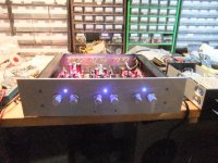
My Mezmerize building has come to a prelimenary end. It is hotroded with 10 ohm resitors. At this time I have not listen to it, but litening test is "ahead" and might show if there any benefits to change to a even "harder hotroding".
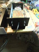
Power in seperate box woth a 50VA 2x15 V AC transformer and 72000uF.
Eivind Stillingen
Power in seperate box woth a 50VA 2x15 V AC transformer and 72000uF.
Eivind Stillingen
Attachments
Hello all,
I am trying to get an older Mezmerize up n running, but honestly my skills in electro are not too impressive.
Seems I am running into some trouble, the output relay does not come on. Is there a way to troubleshoot this part of the board ?
I measure no voltage across the diode at the side of the relay.
2K2 resistor at the circuit with the 7812 measures 5.40 v across,
150 ohm just beside it measures about 9.80 volt
So... It seems to me that the voltage regulator is working, but probably one of the transistors behind it is dead ?
Some help would be really appreciated.
Cheers,
Gijs
The cost difference between a 50VA and 100VA Antek, 2x15V transformer is less than $5:
AS-0515 - 50VA 15V Transformer - AnTek Products Corp
AS-1215 - 100VA 15V Transformer - AnTek Products Corp
For a medium hotrodding of a Mez board, ~200mA, which transformer is better? Is there a benefit of one over the other (or drawbacks?)?
50VA is more than enough, 100VA could be little better subjectively due to lower impedance if you got the box space.
Is there a minimum Amperage rating needed for a hot-rodded mez? The 50/100VA Anteks are listed at 1.5 and 3.3 Amps. Some R-core transformers I've looked at (50VA) are rated between 0.6 and 0.8A.
Three times the both polarities CCSs draw current so not to end up with a hot transformer should be a safe minimum. Constant draw is harder on the components regarding temperature rise.
For a 200 mA hotrod, are you saying 3x200 (600 mA) or 2x200 + 3 x200 (1.2 A)?
- Home
- Amplifiers
- Pass Labs
- Mezmerize DCB1 Building Thread