In my opinion the LL1627 is the best choice because can be used for minimal loss (0.25 dB power loss). The LL1664 or the LL1623 at 3.3K and 3K connectio nare second best with 0.5 dB power loss. THe LL1664 has the advantage of the lower price at least.
The LL1620 is used at 0.8 dB power loss. Usable but not ideal. It's a waste especially considering the already low Pout of the amp. If you want to try the LL1627 I have a pair and you could borrow them.
What primary would you choose for LL1627?
What primary would you choose for LL1627?
2.3K which is a bit higher actually. It's almost 5K per tube.
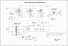
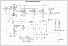
Battery biased 4P1Lx3 PSE Single stage stereo amp
Battery biased 4P1L x 3 PSE Single stage stereo amp
As I have got the pre-ordered OPT (XE-20s) from ISO-Tango in last December. So I decided to build a 4P1L x 3 PSE Single stage Stereo amp (experimental) as I do have a pre-amp which can deliver higher output voltage (over 70V rms) and condenser coupled output), yet with low impedance.
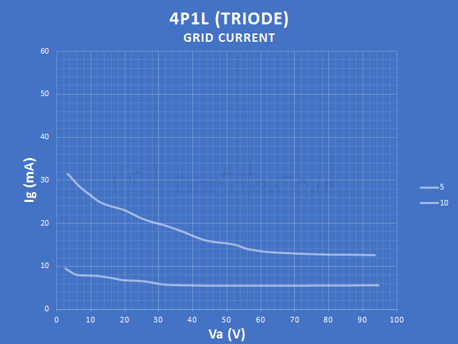
At first, I tried grid leak resister 200K ohm for fixed bias as a standard circuitry, and its output power came out only 4.5W due to the fact of the grid current starts flowing out, so that its bias voltage heads to deeper. It should be pointed out that this 4P1L tends specifically to flow out grid current..
Then, I made another try to replace the grid leak resister with a grid choke.
The outcome was of a minor improvement because of the bias PSU was not strong enough for sustaining lower impedance status...
Finally, I introduced an idea of Battery (14 units of size AA Battery in series for 21 V). Fortunately, the output power jumped up to 7W, and that its sound became further upgraded namely in clarity!
Battery biased 4P1L x 3 PSE Single stage stereo amp
As I have got the pre-ordered OPT (XE-20s) from ISO-Tango in last December. So I decided to build a 4P1L x 3 PSE Single stage Stereo amp (experimental) as I do have a pre-amp which can deliver higher output voltage (over 70V rms) and condenser coupled output), yet with low impedance.
At first, I tried grid leak resister 200K ohm for fixed bias as a standard circuitry, and its output power came out only 4.5W due to the fact of the grid current starts flowing out, so that its bias voltage heads to deeper. It should be pointed out that this 4P1L tends specifically to flow out grid current..
Then, I made another try to replace the grid leak resister with a grid choke.
The outcome was of a minor improvement because of the bias PSU was not strong enough for sustaining lower impedance status...
Finally, I introduced an idea of Battery (14 units of size AA Battery in series for 21 V). Fortunately, the output power jumped up to 7W, and that its sound became further upgraded namely in clarity!
Attachments
This is really interesting! You are helping all who love the 4P1L with your experiments. Many thanks for that.
I want to try 3x4P1L with my Audio Note Trans-152 OPT, which is 2.5K. I use LL1660 interstage and filament bias.
What output would you expect from this arrangement?
I want to try 3x4P1L with my Audio Note Trans-152 OPT, which is 2.5K. I use LL1660 interstage and filament bias.
What output would you expect from this arrangement?
Hi Andy,
Thank you for your comment.
I am sure you can get the same amount of output power: 7~8W with inter-stage and filament bias. I guess your arrangement would be more effective to the grid rectifier current.
In my case, the output power was 8W based on the driving voltage of 23.5V rms .
Thank you for your comment.
I am sure you can get the same amount of output power: 7~8W with inter-stage and filament bias. I guess your arrangement would be more effective to the grid rectifier current.
In my case, the output power was 8W based on the driving voltage of 23.5V rms .
Attachments
4P1L x 3 PSE upgraded (10W in A2 class)
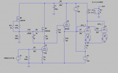
I replaced the battery biasing with a7119 as a direct coupling cathode follower with CCS on my experimental 4P1L PSE amp and that the plate voltage on the 4P1L raised to ca 280V in A2 class.
As a result, the output was increased to 10W with non clipping and that its THD has been improved in all output ranges.
The 4P1Ls in use are running in between 8.5W~9W of plate dissipation.
For verify the durability of 4P1Ls, I shall continue to run on the above conditions for the time being.
Attachments
I replaced the battery biasing with a7119 as a direct coupling cathode follower with CCS on my experimental 4P1L PSE amp and that the plate voltage on the 4P1L raised to ca 280V in A2 class.
As a result, the output was increased to 10W with non clipping and that its THD has been improved in all output ranges.
The 4P1Ls in use are running in between 8.5W~9W of plate dissipation.
For verify the durability of 4P1Ls, I shall continue to run on the above conditions for the time being.
Very nice amp.
How is the transition from A1 to A2 impacts the sound?
Looking at the distorsion chart, you might be able to improve it by choosing a better operating point. I would try to choose the OP in such a manner that both sides swings equally( if for example use -15V then the swing is from +15 to -45, and you dont reach beyond -45V where linearity decreases dramatically). Just a thought.
Best,
Radu
Dear Ale,
Thank you for your comment and interesting chart.
I will try to increase the plate current of 7119 a little bit more and see what would be happened.
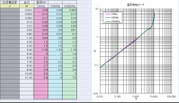
For your reference I attached a distortion characteristic graph.
It is apparent that transition point from A1 to A2 is at around 5~6W.
Hiro
Thank you for your comment and interesting chart.
I will try to increase the plate current of 7119 a little bit more and see what would be happened.
For your reference I attached a distortion characteristic graph.
It is apparent that transition point from A1 to A2 is at around 5~6W.
Hiro
Attachments
Dear Ale,
Thank you for your comment and interesting chart.
I will try to increase the plate current of 7119 a little bit more and see what would be happened.
For your reference I attached a distortion characteristic graph.
It is apparent that transition point from A1 to A2 is at around 5~6W.
Hiro
Hi Hiro,
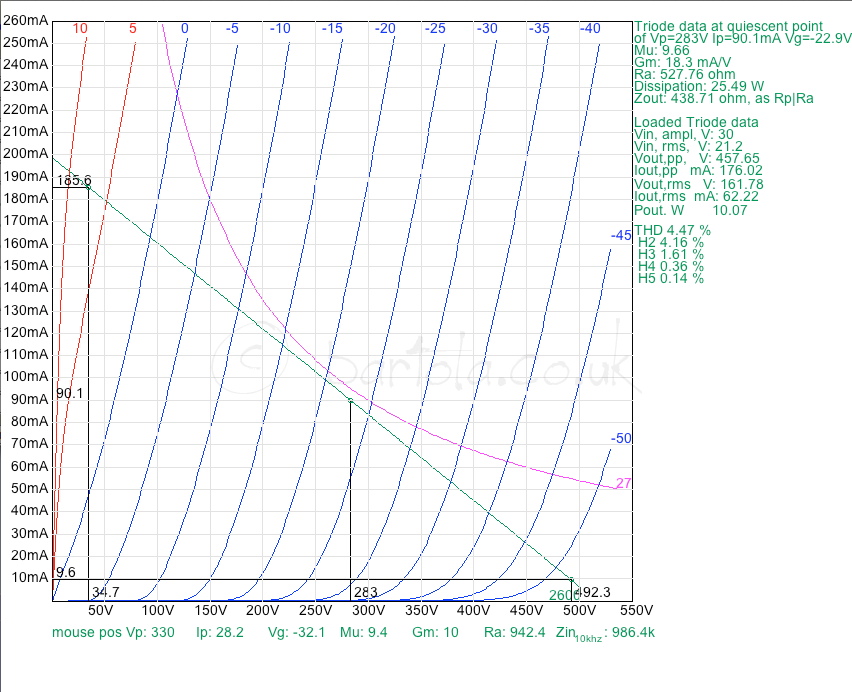
Very interesting measurements. I never run the 4P1L higher than 250V. I'd be interesting to see what is the impact on the lifespan. Anyway, I tried to replicate your operating point to see how it matches with the ideal model. It does pretty well in fact. Here is the ideal A2 point. However we well know that the grid current will kick in way before this point. Also the Zaa is set to 2k6 (your reflected 8 ohm load plus Ra from your primary but doesn't take into account your secondary resistance).
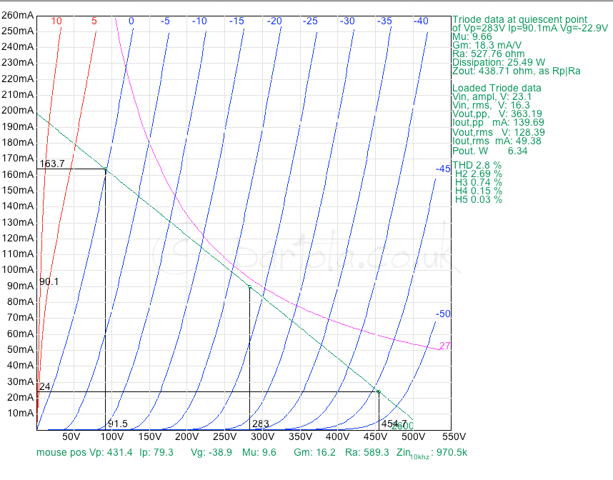
When you push this to the limits you can see that 10W is suffering more from the curve crunching at the right-bottom side:
I suspect that it won't help too much increasing the driver current. However is worth trying to see if there is any improvement
")
Cheers
Ale
How (hw / sw) did you obtain that data?
Japanease free soft ware, running on Excell base supposedly.
Hiro
Hi Hiro,
Very interesting measurements. I never run the 4P1L higher than 250V. I'd be interesting to see what is the impact on the lifespan. Anyway, I tried to replicate your operating point to see how it matches with the ideal model. It does pretty well in fact. Here is the ideal A2 point. However we well know that the grid current will kick in way before this point. Also the Zaa is set to 2k6 (your reflected 8 ohm load plus Ra from your primary but doesn't take into account your secondary resistance).
Dear Ale,
Thank you very much for a chart and detailed analysis of my 4P1L PSE amp.
I performed it in the other channel too.
I noticed that the operation point was shifted in 8~10W during the measurement:
1) Grid bias of 4P1L: -23.1V( 1W), -23.5V(10W)
2) Cathode current of 4P1L: 92.1mA(1W), 99.8mA(10W)
3) Plate current of 7119(CF): 13.1mA(1W), 16.0mA(10W)
Hiro
Attachments
Hi Hiro,
The 7mA increase you see in the cathode is actually the grid current. You can see from my previous simulation that is likely you are driving the grid to above +5V when running in 10W (class A2). At this point, if you look at my previous grid current trace, the current is greater than 6mA.
Cheers,
Ale
- Home
- Amplifiers
- Tubes / Valves
- One more 4P1L SE