Hi,
Stajo refers to the Itch phono preamp which uses a 6SN7 as the second stage after RIAA correction.
You're welcome. Use it wisely.
Ciao,")
Stajo refers to the Itch phono preamp which uses a 6SN7 as the second stage after RIAA correction.
Oh, and thanks for the articles. Very interesting.
You're welcome. Use it wisely.
Ciao,
No. Replacing current 6SN7s
Any circuit can be re-designed. I'm sure the designer can help you.
No need for new design hopefully. Slightly higher mu tubes is enough.
I don't think you understand. The circuit was designed for that particular tube. You can't just pop another tube in there and expect it to work. The circuit has to be optimized and redesigned for a different type of tube.
Hi,
With a B+ of 300VDC the biasing resistors should be changed to 820R each and the (is it 24K now?) divider for the top tube to 47K.
Based on what I read from Rev. 1.1
Maybe not optimal but it should work O.K.
Ciao,
Are this comment for a scenario where B+ for input tubes are raised from 280 to 300?
There's a high likelihood that the cascode ccs will need to be abandoned or reconfigured for lower current anyhow.
The reason being that the higher current is likely to increase the noise levels of the stage and that's of course the last thing we want to do.
Nonetheless it's worth to give it a try so we can at least have a "life" example that will show a relationship between Ia, gm and I/f for LF applications.
This is one of the many reasons this circuit was brought to the attention of the readers here.
Often people opt for high gm tubes with spectacular Req values (at UHF) based on the IME false premise that the 2.5/gm formula will wave its magic wand on their LF circuit.
While, and again this is only from personal experience, high gm valves certainly have their merit in retrieving fine detail, they also come with a set of cons. One of them is stability at LF which often requires counter measures which work against low noise anyway...
Ciao,
Its a matter of finding an acceptable balance between flicker and hiss. The trimmer should show. You may need some extra B+ for ease of experiments. The DMOS is not good CCS under 20mA. If to stay low in the end better vary a BF245C or something JFET alike instead of the DMOS when in the listen. Like in the pic. Flicker is nuisance, then again 5-6mS total at 1mA for each section take us not too far for hiss by modern standards. Maybe a tube like 6C4Π-ΕΒ with about 9mS at 5mA Ia. It would need much higher voltage at the plate vs. ECC88 at 0 Vgk though.
*By the way the Itch keeps at a good Ia/gm ratio for flicker.
Attachments
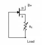
There doesn't appear to be enough B+ to run a cascode Mosfet CCS. I'm measuring only about 1 VDC drop across it (about 22.6V on the plates @ 19.something mA).
27mA Ia 22V across the tubes in my models with your 40R CCS setting resistor. 19.8mA 15.75V with 63R.
How much B+ and setting R needed it will surely deviate from the models in practice.
Hi,
At a B+ of 300VDC but it's not that critical.
Exactly. At this point I don't think anyone can tell for sure when it's going to occur.
So much speculation on the subject of noise of all kinds at this point in time that it's hard to draw definite conclusions yet.
It will vary some from one tube sample to another etc. for sure.
That's also a possibility. As is the 6C3Pi-EB. Dual triodes are a bit easier to // though, it's more compact so that makes it a littler less prone to wild oscillation. Grid stoppers are no option in such a circuit.
BTW, one thing that did surprise me a bit is the predominance of odd harmonic distortion in the sim. I did not expect that.
More like something you'd expect from a balanced version of the MC stage (as like in a PP stage) or a penthode.
It can be cancelled out somewhat by adding a modest buffer should it bother anyone....
I vaguely recall having tried a BF245B at one point in time. Didn't work.
I noticed right from the start that you kept the current through the tubes at the lower end of the spectrum.
Something that also helps to reduce noise is to keep the heaters slightly under the regular voltage. Say 6VDC instead of 6.3VDC etc.
At the current current settings of the tubes in the Itch they should last a lifetime.
Ciao,
Are this comment for a scenario where B+ for input tubes are raised from 280 to 300?
At a B+ of 300VDC but it's not that critical.
Its a matter of finding an acceptable balance between flicker and hiss.
Exactly. At this point I don't think anyone can tell for sure when it's going to occur.
So much speculation on the subject of noise of all kinds at this point in time that it's hard to draw definite conclusions yet.
It will vary some from one tube sample to another etc. for sure.
Maybe a tube like 6C4Π-ΕΒ with about 9mS at 5mA Ia.
That's also a possibility. As is the 6C3Pi-EB. Dual triodes are a bit easier to // though, it's more compact so that makes it a littler less prone to wild oscillation. Grid stoppers are no option in such a circuit.
BTW, one thing that did surprise me a bit is the predominance of odd harmonic distortion in the sim. I did not expect that.
More like something you'd expect from a balanced version of the MC stage (as like in a PP stage) or a penthode.
It can be cancelled out somewhat by adding a modest buffer should it bother anyone....
If to stay low in the end better vary a BF245C or something JFET alike instead of the DMOS when in the listen.
I vaguely recall having tried a BF245B at one point in time. Didn't work.
*By the way the Itch keeps at a good Ia/gm ratio for flicker.
I noticed right from the start that you kept the current through the tubes at the lower end of the spectrum.
Something that also helps to reduce noise is to keep the heaters slightly under the regular voltage. Say 6VDC instead of 6.3VDC etc.
At the current current settings of the tubes in the Itch they should last a lifetime.
Ciao,
Last edited:
BTW, one thing that did surprise me a bit is the predominance of odd harmonic distortion in the sim. I did not expect that.
More like something you'd expect from a balanced version of the MC stage (as like in a PP stage) or a penthode.
It can be cancelled out somewhat by adding a modest buffer should it bother anyone....
Ciao,
Don't trust some ECC88 Spice model in the starved plate 0Vgk region until you will FFT the real thing.
I noticed right from the start that you kept the current through the tubes at the lower end of the spectrum.
Something that also helps to reduce noise is to keep the heaters slightly under the regular voltage. Say 6VDC instead of 6.3VDC etc.
At the current current settings of the tubes in the Itch they should last a lifetime.
Ciao,
Its at 6.1V on the suggested PSU schematic for that reason. Even in the early build at page #1.
I vaguely recall having tried a BF245B at one point in time. Didn't work.
Maybe to parallel a couple?
Hi,
I'm sure you're right. It's unknown territory for all Spice models I suppose.
Absolutely. I spotted it right away.
I just mentioned it because nobody else seems to have taken notice of it in the entire thread.
Good to see you know about this.
Ciao,
Don't trust some ECC88 Spice model in the starved plate 0Vgk region until you will FFT the real thing.
I'm sure you're right. It's unknown territory for all Spice models I suppose.
Its at 6.1V on the suggested PSU schematic for that reason. Even in the early build at page #1.
Absolutely. I spotted it right away.
I just mentioned it because nobody else seems to have taken notice of it in the entire thread.
Good to see you know about this.
Ciao,
Hi,
What happened is that the voltage on the plate went up from 12VDC (compared to a single BF245A) to a higher voltage (can't remember exactly how much it was, this is more than 20 years ago) and the entire stage lost much of the gain.
Mind you, I didn't thoroughly investigate this. It was just a quick experiment just in case I ran out of BF245As.
While looking for a replacement of the BF245A lately I also found some BF256A
which have an Idss which is pretty close to the BF245A.
I haven't really compared the rest of the data side by side though but it's the Idss of the J-Fet that makes the circuit "tick" from what I gather.
I'm by no means an expert in anything solid state though.
Ciao,
Maybe to parallel a couple?
What happened is that the voltage on the plate went up from 12VDC (compared to a single BF245A) to a higher voltage (can't remember exactly how much it was, this is more than 20 years ago
) and the entire stage lost much of the gain.Mind you, I didn't thoroughly investigate this. It was just a quick experiment just in case I ran out of BF245As.
While looking for a replacement of the BF245A lately I also found some BF256A
which have an Idss which is pretty close to the BF245A.
I haven't really compared the rest of the data side by side though but it's the Idss of the J-Fet that makes the circuit "tick" from what I gather.
I'm by no means an expert in anything solid state though.
Ciao,
BF245B vs. 245A gave double the IDSS and the plates biased higher is one logical scenario. Then the multiplier transistor could have turned insufficient at that Ia demand?Hi,
What happened is that the voltage on the plate went up from 12VDC (compared to a single BF245A) to a higher voltage (can't remember exactly how much it was, this is more than 20 years ago
Mind you, I didn't thoroughly investigate this. It was just a quick experiment just in case I ran out of BF245As.
While looking for a replacement of the BF245A lately I also found some BF256A
which have an Idss which is pretty close to the BF245A.
I haven't really compared the rest of the data side by side though but it's the Idss of the J-Fet that makes the circuit "tick" from what I gather.
I'm by no means an expert in anything solid state though.
Ciao,
Measure the IDSS of your original JFET in the well ticking pre-pre. Then select for same IDSS no matter if its a compatible type. JFETs vary over a largish IDSS range even in the same type's A,B,C, etc. subcategory.
JFET matching
Hi,
Truth be told, I have no idea.
It's an MPSA14 (500mW?) and it didn't give me any smoke signals or anything...
Either way, at this point it's just speculation from my side.
If the cascaded FETs don't work we can still fall back on the BF245A. I'll just ask a friend to order a 100 from RS in Spain or something.
I'd love to but the darn thing got stolen along with a hole bunch of other stuff not so long ago so I'll need to rebuild from scratch.
Ciao,
Truth be told, I have no idea.
It's an MPSA14 (500mW?) and it didn't give me any smoke signals or anything...
Either way, at this point it's just speculation from my side.
If the cascaded FETs don't work we can still fall back on the BF245A. I'll just ask a friend to order a 100 from RS in Spain or something.
Measure the IDSS of your original JFET in the well ticking pre-pre.
I'd love to but the darn thing got stolen along with a hole bunch of other stuff not so long ago so I'll need to rebuild from scratch.
Ciao,
Last edited:
- Home
- Source & Line
- Analogue Source
- Valve Itch phono