There was a very nice article in the middle of the nineties in Wireless World about exactly such a thing. It used a center tapped inductor in the output stage where the center tap was fed by a battery (I think) and two mosfets in balanced configuration were connected at either ends of the inductor. I think the author suggested usind an appropriately rated toroid transformer as inductor. I remember the iddle current was 6A (or was 3A per mosfet?).
In addition the driver circuit used a intestage transformer to drive the mosfets.
The whole schematic, in my mind now, reminds me of a inductor coupled zen amp but I'm quite sure there were other differences that I've now forgotten.
I got most parts but stumbled on the interstage audio transformer (I never found a sufficiently high specced part to use) so I never finished building it. I guess I didn't know where to look back then.
It's well worth digging that article up if yoiu're after that sort of thing.
Unfortunately, I haven't got the article with me right now but if you email me I'll try to find it and scan it when I go back home during easter.
Regards
Stelios
Maybe I've posted too soon as the circuit I'm referring too really resembles the ZV7 mentioned above - if you can imagine the final stage being driven by an emitter follower bjt and that in itself connected to the gain stage through an intestage transformer/inductor. Funnily enough, the idle current seems to be the same in both designs !
There was a very nice article in the middle of the nineties in Wireless World about exactly such a thing. It used a center tapped inductor in the output stage where the center tap was fed by a battery (I think) and two mosfets in balanced configuration were connected at either ends of the inductor. I think the author suggested usind an appropriately rated toroid transformer as inductor. I remember the iddle current was 6A (or was 3A per mosfet?).
In addition the driver circuit used a intestage transformer to drive the mosfets.
It's well worth digging that article up if yoiu're after that sort of thing.
Stelios
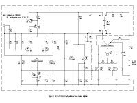
I think this is the circuit you mean, Stelios (pic 1)
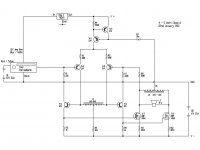
The latest issue is much cleaner and now looks like this (pic 2).
The offset control feedback (Tr8/9) has been replaced by source degeneration, trading efficiency for simplicity.
Battery B1 has gone along with the on/off switch, replaced with a small regulator, Reg1, the reg input now serves as on/off control (I'm using a quality car radio as signal source)
As shown it's biased for about 5W output, since that's all I need, and is powered by 2 little 6V 12A SLAs. Biasing for more power is just a matter of increasing supply voltage (B2) and adjusting R5 for required quiescent current – oh, and increasing the heat sinks. For a couple of years I ran it at 32W driving Monitor Audio R652 (or something), now I use horns I only need 5W.
Sorry about L1, you can find it here: common.leocom.jp/pdfcat/catalogpage/1_1840.pdf
If I have another go I'll probably remove it.
Attachments
Last edited:
Found it, the Andy Grove design was in HiFi World February 1996 with an alternative by Chris Found, with better linearity. Both were specified at 15W with a BUZ346 output device. There was a follow up in June 1996 in the letters page clarifying a few typos, which I have a copy of.
Found it, the Andy Grove design was in HiFi World February 1996 with an alternative by Chris Found, with better linearity. Both were specified at 15W with a BUZ346 output device.
That sounds interesting, any chance you could pop the circuit(s) up ?
I have redrawn the Chris Found version and uploaded here: http://www.diyaudio.com/forums/attachment.php?attachmentid=347450&stc=1&d=1368018940
Attachments
![2013-05-08 21-13-35_LTspice IV - [Chris_Found_Class_A].png](/community/data/attachments/326/326985-8f7a4420ef3e7c44aff98fe3b020059d.jpg)
I have redrawn the Chris Found version and uploaded here: http://www.diyaudio.com/forums/attachment.php?attachmentid=347450&stc=1&d=1368018940
Ah..single-ended FET but not inductance loading. There again mine isn't SE. Nice to see though.
I have a test amplifier using a 12bh7 as a voltage gain stage driving a mosfet follower.
I like the sound if it. I think it may sound better than class a with a resistive load.
Supply voltage on the mosfet is about 12 volts and the bias current is about 1.5 amp.
I used some 10MH 20A .11 ohm gapped chokes. I only plan to use the amplifier above 100HZ.
The speaker is connected to both sides of the choke without a coupling capacitor.
I like the sound, though it is not completely ready for use.
I use a voltage divider from the +12 to get about 4 volts on the gate. I had to add a capacitor on the divider to reduce noise on the output. I used a 50K resistor from the divider to the gate. I capacitor coupled the 12bh7 to the gate.
You may want a thermisor to adjust the current. The mosfets I use have a positive temperature coefficient in the operating range.
A thermistor in the divider should solve any runaway problems.
I think it is a worthwhile thing to do. Your choke requirements will be somewhat larger if you need ot go lower in frequency.
The output transformer is giving inductance loading, so you get the efficiency advantage.
Yes, the transformer does give better efficiency but it is not inductance loading.
The current in a transformer varies as the signal which is why good sound o/p transformers are so very expensive. With inductance loading the current does not vary, it is effectively a current source, which makes it a far less critical component.
However, when implemented SE the inductor is highly magnetised by the constant current which makes it very big. It also requires a large capacitor to couple the speaker. Both these problems can be fixed by using push-pull where the magnetising currents cancel and the cap is not required.
In the circuit I show (which will easily scale to 50W) there are no coupling capacitors and the output inductor is very easy to make at home or you could just use an old mains toroid.
Attachments

Late reply...
If only I had checked this thread an hour after posting !")
I checked the link but it's now expired I'm afraid ..
You know, the thought never occurred to me to replace the inductor with resistors ... At least I could have managed to listen to the amplifier that way.
On the other hand, do you think a suitably chosen audio transformer could play the inductor role instead ? There's many established firms that supply such small signal parts e.g. Jensen, Cinemag, Amplimo, Neutrik etc. Perhaps one could use such a part with a dummy load on the secondary ?
The design could be modified of course to use an interstage transformer instead of an inductor (which would make the search for the part much easier) but I guess that was not the original intention.
There are now boutique audio transformer manufacturers that produce bespoke output transformers for transistor amplifiers so I suppose one could order an inductor for the output stage with them - although it would still be way out of my budget.
Having both inductors designed specifically for wideband audio I guess would really push the boundaries for such a project - although it might very well prove that the extra expense is not justified by the resulting sonic gains...
Regarding the more power: would it require changing the output inductor in order to handle the higher dissipation ?
I'd love to be able to finally complete this project and thus be able to compare the version with degeneration with the one with the servo.
My main worry, however, would be providing some kind of speaker protection that would be fast enough eventually - I would worry about connecting any amplifier with DC cancelation on the output across a vintage speaker !
If only I had checked this thread an hour after posting !
I checked the link but it's now expired I'm afraid ..
You know, the thought never occurred to me to replace the inductor with resistors ... At least I could have managed to listen to the amplifier that way.
On the other hand, do you think a suitably chosen audio transformer could play the inductor role instead ? There's many established firms that supply such small signal parts e.g. Jensen, Cinemag, Amplimo, Neutrik etc. Perhaps one could use such a part with a dummy load on the secondary ?
The design could be modified of course to use an interstage transformer instead of an inductor (which would make the search for the part much easier) but I guess that was not the original intention.
There are now boutique audio transformer manufacturers that produce bespoke output transformers for transistor amplifiers so I suppose one could order an inductor for the output stage with them - although it would still be way out of my budget.
Having both inductors designed specifically for wideband audio I guess would really push the boundaries for such a project - although it might very well prove that the extra expense is not justified by the resulting sonic gains...
Regarding the more power: would it require changing the output inductor in order to handle the higher dissipation ?
I'd love to be able to finally complete this project and thus be able to compare the version with degeneration with the one with the servo.
My main worry, however, would be providing some kind of speaker protection that would be fast enough eventually - I would worry about connecting any amplifier with DC cancelation on the output across a vintage speaker !
I think this is the circuit you mean, Stelios (pic 1)
The latest issue is much cleaner and now looks like this (pic 2).
The offset control feedback (Tr8/9) has been replaced by source degeneration, trading efficiency for simplicity.
Battery B1 has gone along with the on/off switch, replaced with a small regulator, Reg1, the reg input now serves as on/off control (I'm using a quality car radio as signal source)
As shown it's biased for about 5W output, since that's all I need, and is powered by 2 little 6V 12A SLAs. Biasing for more power is just a matter of increasing supply voltage (B2) and adjusting R5 for required quiescent current – oh, and increasing the heat sinks. For a couple of years I ran it at 32W driving Monitor Audio R652 (or something), now I use horns I only need 5W.
Sorry about L1, you can find it here: common.leocom.jp/pdfcat/catalogpage/1_1840.pdf
If I have another go I'll probably remove it.
I just came across the new Carnhill site:
Audio Maintenance Limited Inductors
Their inductors / input transformers look impressive ! I haven't checked the specs. yet but maybe one of their multi-tapped inductors would be suitable AND readily available locally !
On second thought, I think I'd prefer the original: 6W dissipation seems a bit too much for a low power amp to me (even for a 50W version) - my environmental sensitivities kicked in here.
Not much change there in terms of the number of batteries then. But having the same kind of batteries throughout might make practical sense and I've read that SLAs are better sonically ? would you agree with that last statement?
That's a great idea but do I see the word "DAB" in there ? tut, tut..
Which ones if I may ask ?
An active horn system (or even non-horn system) with 3 pairs of this amp. would be quite something! would it not?
Please don't.
Still, it would be useful to have a version without the inductor for the benefit of those builders on budget or not able to readily source the part.
Audio Maintenance Limited Inductors
Their inductors / input transformers look impressive ! I haven't checked the specs. yet but maybe one of their multi-tapped inductors would be suitable AND readily available locally !
The offset control feedback (Tr8/9) has been replaced by source degeneration, trading efficiency for simplicity.
On second thought, I think I'd prefer the original: 6W dissipation seems a bit too much for a low power amp to me (even for a 50W version) - my environmental sensitivities kicked in here.
Battery B1 has gone along with the on/off switch, replaced with a small regulator, Reg1, the reg input now serves as on/off control
...
and is powered by 2 little 6V 12A SLAs.
Not much change there in terms of the number of batteries then. But having the same kind of batteries throughout might make practical sense and I've read that SLAs are better sonically ? would you agree with that last statement?
(I'm using a quality car radio as signal source)
That's a great idea but do I see the word "DAB" in there ? tut, tut..
now I use horns I only need 5W.
Which ones if I may ask ?
An active horn system (or even non-horn system) with 3 pairs of this amp. would be quite something! would it not?
If I have another go I'll probably remove it.
Please don't.
Still, it would be useful to have a version without the inductor for the benefit of those builders on budget or not able to readily source the part.
Last edited:
I checked the link but it's now expired I'm afraid ..
Farnell do still list it, Stelios, it's now here:
A262A1E - OEP (OXFORD ELECTRICAL PRODUCTS) - TRANSFORMER, 6.3+6.3:1+1, 150OHM | Farnell UK
But, by all means, do try your own solution. The part I specified is the best one I could find but you might well find something better.
I'll get back with a much fuller response soon.
In reply to OP - I can't help with a SE amp - but here is my balanced amp, choke loaded. The circuit was originally inspired by the Hi Fi World circuit referenced above (Andy Grove/ Chris Found) but I didn't work out the output stage until i read the Wireless article in 1999 - I copied this stage outright, including using a power toroid as an output choke. In the end it was simpler to make the input stage balanced, since the out put is balanced, but I've used the same feeback to source (Current feedback?) as used by Andy Grove.
http://www.diyaudio.com/forums/solid-state/212424-balanced-class-fet-amplifier.html
http://www.diyaudio.com/forums/solid-state/212424-balanced-class-fet-amplifier.html
If only I had checked this thread an hour after posting !
Regarding the more power: would it require changing the output inductor in order to handle the higher dissipation ?
Yes. Use the same VA rating as the proposed amplifier power wattage.
Oh, and check FETs voltage rating is greater than the peak speaker voltage.
My main worry, however, would be providing some kind of speaker protection that would be fast enough eventually - I would worry about connecting any amplifier with DC cancelation on the output across a vintage speaker !
I'm happy not to use speaker protection, it's hard to see what could damage the speakers without taking the fuse out first. But you must assess the risk yourself.
The point about deleting battery B2 is that it also removes the 10A switch, switching the amp OFF when the source goes OFF - and it gets rid of the relay. Its a much tidier solution.Not much change there in terms of the number of batteries then. But having the same kind of batteries throughout might make practical sense and I've read that SLAs are better sonically ? would you agree with that last statement?
I have my own-design low-profile 'bifurcated' stereo horn system and disguised it as the end of the room (its about 160mm deep)Which ones (horns) if I may ask ?
What state is your amp in now? Can you complete it using the Farnell part I pointed to?
Farnell do still list it, Stelios, it's now here:
A262A1E - OEP (OXFORD ELECTRICAL PRODUCTS) - TRANSFORMER, 6.3+6.3:1+1, 150OHM | Farnell UK
But, by all means, do try your own solution. The part I specified is the best one I could find but you might well find something better.
I'll get back with a much fuller response soon.
A-ha! brilliant ! I think I've come across this but as I was looking for a tapped inductor...
Which brings me to the question I wanted to ask ever since I started this project: which side do you connect ? the 150 ohm or the 6.3 ohm? I guess you leave the other side open circuited - I'm starting to remember the original article now
Thanks for this - I'm always too impatient with the farnell / rswww sites to ever be able to find anything in there...
I think I'll start with this part and when I'll have more disposable income I might try to find sth. fancier
Ah yes, its not clear at all is it? Its the primary, Stelios, 150 ohm. Looking at the PDF, use pin A1 as start, connect A2 to A3 as the centre tap then A4 is the other end. The way they've run the pin-out is very confusing - I thought for a minute I'd gotten mine wrong! If you're unsure, wire it up then put a signal on one half and check that the voltage doubles across the full winding. And yes, leave the secondary open.A-ha! brilliant ! I think I've come across this but as I was looking for a tapped inductor...
Which brings me to the question I wanted to ask ever since I started this project: which side do you connect ? the 150 ohm or the 6.3 ohm? I guess you leave the other side open circuited
I'm happy not to use speaker protection, it's hard to see what could damage the speakers without taking the fuse out first. But you must assess the risk yourself.
err... a badly soldered board perhaps with leads flying about the place ?
I get nervous every time I turn on my old MF amps - but maybe that's just me.
The point about deleting battery B2 is that it also removes the 10A switch, switching the amp OFF when the source goes OFF - and it gets rid of the relay. Its a much tidier solution.
oh! I'd still feel much safer with a switch at the output stage power supply even if this is a much more elegant solution.
I have my own-design low-profile 'bifurcated' stereo horn system and disguised it as the end of the room (its about 160mm deep)
This sounds very impressive. Disguising horns of that size is quite an achievement in itself too.
What state is your amp in now? Can you complete it using the Farnell part I pointed to?
Well, I think I might have built only one channel as I only had one toroid that would withstand 6A at the time. It was 10yrs or more ago when I built it so I'm not sure. I also fear I could have damaged the mosfets based on the number of times I handled them without taking any precautions for static ..
All that was needed was the first stage inductors - and a second toroid! I think I wanted to try it out first before going out to order two same toroids as they are the most pricey part.
Well, I guess I've waited too long. By now of course the SLA's will be good for the recycling tip..
It's stored away back in Greece so I'll dig it up when I'll go back for Easter.
Ah yes, its not clear at all is it? Its the primary, Stelios, 150 ohm. Looking at the PDF, use pin A1 as start, connect A2 to A3 as the centre tap then A4 is the other end.
....
And yes, leave the secondary open.
Many thanks !
Well, now I really have no excuse for not completing the project..
- Home
- Amplifiers
- Solid State
- MOSFet Class A SE with inductive loading.