I tried same way and with every connection there is a drop in voltage.You can try to connect inductors to power only the wm8804 (L5,6) and after that to power only ES9023 (L1,2,3) so you can detect in wich part of dac you have that overconsumption.
My idea is to try to isolate the stage wich eating too much current.
With single L6 connected its 4.78V ,After L5 4.36V, L4 caused 4.02V,when all connected ,reading was 3.35V.
earlier I though that only L3 was an issue,but testing different way concluded ,with every connection of 'L ',there is a voltage drop.
I did not remove any L1 or L2 while taking reading of WM/ESS. I will do that.
Last edited:
spirovious: your power supply has much too high input voltage. It seems that you are using the single tap output with the IC2 regulator and its potentiometer. Now when the input voltage is around 26V (to get out the maximum of 24V) and the output voltage is 5V and let's assume that the output current is 50mA, then the power dissipation for that regulator is: (26V - 5V) * 50mA = 1.0W
If that regulator is LM317T, then it should not be used without a heat sink when the power dissipation exceeds 0.25W. So you need the change your transformer to one with lower secondary voltage or put a heat sink on that poor regulator.
As the output voltage has dropped dramatically, it might indicate that the heat has damaged the regulator. So I'd change those heated up parts as well.
About changing the transformer: this can only be done when you are not using the other dual output for anything that would need so high output voltages.
Last edited:
Thanks tuo,
The best part is that DAC worked earlier with same power supply and then this issue started.Yes heatsink can be useful,but not sure if problem get solved.
Also as atupi suggested,adding a resistor and measuring the result may conclude something.Also one person suggested to change the input resistor in power supply from 1ohm 2W to 100ohm 3W and use heatsink.
I will also take readings after removing L1 L2 one by one to know which section is giving extra load on power supply.
@ darshanjoshi - Diode is the LED on the power supply. A couple more simple things to check: Turn off the DAC and disconnect the power supply. Check for a residual (stored) current on the PS (unplugged / switched off) and the DAC. A little bulb can be used to dissipate a charge if one exists. The pic shows one for larger power supplies but soldering some wires to a flashlight battery will work here. Just touch those wires to the power terminals on each board for a few seconds.
How to....
The 1, 5 and 20 sequence appears related to timing/sync as Gary and Marce describe, but clearing all the stored voltages might help pinpoint something.
I am new at this. I will check the video and report back my findings.
If there is issue with PS, I can check with one of my friends PS who has also build Subbu V3 and working fine.
Yes heatsink can be useful,but not sure if problem get solved.
You have a problem with the heat dissipation. The regulator has to waste the power between input and output voltages as heat because the energy there is not going to disappear. And that is in this case around that 1W reading.
Also one person suggested to change the input resistor in power supply from 1ohm 2W to 100ohm 3W and use heatsink.
Yes, the first one will lower the input voltage to the regulator, making the problem smaller, so a smaller heatsink will be enough.
Right,
NOW it's finished.
Got the new transformer. The DC voltage before the pass transistor has gone from 20.1 volts to 11.5 volts. The little heatsink on the transistor went from "ouch, my finger!" to "mmm, warm"
Much better, now I don't have to worry about cooking things by leaving it on for hours at a time.
Looks like I won't need to take up your kind offer Bob.")
Thanks everyone,
Mark
NOW it's finished.
Got the new transformer. The DC voltage before the pass transistor has gone from 20.1 volts to 11.5 volts. The little heatsink on the transistor went from "ouch, my finger!" to "mmm, warm"
Much better, now I don't have to worry about cooking things by leaving it on for hours at a time.
Looks like I won't need to take up your kind offer Bob.
Thanks everyone,
Mark
Right,
NOW it's finished.
Got the new transformer. The DC voltage before the pass transistor has gone from 20.1 volts to 11.5 volts.
Hi,
Which transformer did you end up using?
Hi,
Which transformer did you end up using?
Block 2.8VA 6V single secondary.
This one:
Buy PCB Transformers PCB mount transformer 2.8VA 1x6 o/p Block VB 2,8/1/6 online from RS for next day delivery.
Seems to work a treat. The previous one was the 9v version, which was WAY higher than spec, even taking the regulation into account, so your mileage may vary...
Edit: Oh, and don't believe RS when the say "next day delivery" More like next week delivery...
Cheers,
Mark
Hi All,
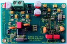
As promised some times ago, pics about Subbu DAC V3 PCB voltage.
Remind : measures were taken without ES9023 DAC chip soldered.
Values shown & measured are relative to this DAC unit.
No wires/connexions/short at the input nor at the output. (Left & Right I/O and SPDIF unwired)
From what I've noticed previously, consider those values as average.
Your values may vary from those reported here.
I'll post another set of pics with ES9023 soldered soonly.
Hope this helps for troubleshooting sessions
Regards
Phil
Attachments
Last edited:
Hi Darshanjoshi,WM
1 3.280 1.640 20
2 3.280 3.290 19
3 0.000 0.000 18
4 0.039 0.026 17
5 3.280 0.000 16
6 3.290 3.520 15
7 3.290 3.520 14
8 0.000 0.000 13
9 1.700 0.029 12
10 0.550 0.770 11
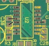
Your WM8804 values from pin 13 to 16 seems to be faulty to me.
Please check R4/R5/R6 values whose should be close to 0.029/3.52/3.52 according to your measures.
I suggest you to clean the right side/section of WM8804 using flux and desolder braid.
I suspect a short, but can't understand where and how do you pick a 3.52v value there....
Maybe I'm wrong and I'll complete my input with ES9023 soldered values soonly
Would you please check again and report ?
Regards
Phil
Last edited:
A reference to Phil's work on the voltage readings has been added to the thread's first post. Thanks Phil - a highly useful and appreciated addition to the project. 
You're welcome Bob !
Thank you for your kind words, I'm just a bit late
Kudos for your work and initiative
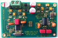
As promised this morning, measures with ES9023 DAC chip soldered.
I've only reported about voltage read on ES9023 pins.
Black : no changes - Yellow : changes
As expected, other values aren't affected.
Forget to mention : the DAC is working fine
Remind :
- Values shown & measured are relative to this DAC unit.
- No wires/connexions/short Left & Right I/O and SPDIF unwired.
- Your values may vary from those reported here.
- Consider those values as average.
Regards
Phil
Thank you for your kind words, I'm just a bit late
Kudos for your work and initiative
As promised this morning, measures with ES9023 DAC chip soldered.
I've only reported about voltage read on ES9023 pins.
Black : no changes - Yellow : changes
As expected, other values aren't affected.
Forget to mention : the DAC is working fine
Remind :
- Values shown & measured are relative to this DAC unit.
- No wires/connexions/short Left & Right I/O and SPDIF unwired.
- Your values may vary from those reported here.
- Consider those values as average.
Regards
Phil
Attachments
Last edited:
Today tried with 3 DC batteries each of 1.5V.The combined voltage was recorded as 4.57V before connecting DAC.After I connected DAC,the main input voltage recorded was only 1.18V.So Aagin connected to my power supply.I tried same way and with every connection there is a drop in voltage.
With single L6 connected its 4.78V ,After L5 4.36V, L4 caused 4.02V,when all connected ,reading was 3.35V.
earlier I though that only L3 was an issue,but testing different way concluded ,with every connection of 'L ',there is a voltage drop.
I did not remove any L1 or L2 while taking reading of WM/ESS. I will do that.
When removed L1,main voltage reading came as 4.52V.
Rest of readings were almost similar to what I reported in my last post.When connected L1,total input voltage dropped to 2.37V.
When L3 and L5 are not connected,main input voltage shows 4.89V.
After I connect L5,it drops to 4.57-4.62V. After L3 in,almost 2V drop and reading comes to 2.37V.
When L2 removed,readings on Q are 2.14, 0, 1.37V.
I added a heatsink to power regulator.Still cant find the issue.Working DAC stopped only after I cleaned PCB with IPA.So what can be the issue?
FIY - There was an earlier reference to what the V3 will be pushing and some hum problems with that setup. An elaborate system was applied that solved the issue, but the culprit was actually a current leaking back into the chassis due to a wide-head PCB mounting screw touching the negative supply rail.
Here is a link to the completed project that was done side by side with the JP/Subbu DAC. Combination sounds great with the V3 pulling in all the detail and dynamics.
BLAT V4.0
Here is a link to the completed project that was done side by side with the JP/Subbu DAC. Combination sounds great with the V3 pulling in all the detail and dynamics.
BLAT V4.0
Attachments
 Thank you Bob.
Korben,
Your photographs with added words are impressives & usefull : what do you use please ?
Thank you
Scanner, iPhone camera, MSPaint.
Regards
Phil
- Home
- Source & Line
- Digital Line Level
- Build thread - building the Subbu DAC V3 SE