Jens, any chance to continue with the super leach boards?
Ditto on that!
Hi All,
I have been really busy with family and work for the last 2 years.... so time and energy for DIYaudio has be limited.
Let me know what version you want to use, and I will generate a set of gerbers to match...
I can even make the silkscreen so it reflects the group buy year - ?
If the DIYaudio shop wants to offer boards, I'm open to this also - let me know - thanks
Warm regards
Jens
The silkscreen idea sounds neat!
I'm glad you're still around, even if sporadically. I am also quite busy all the time, even weekend, but I have been thinking about my amp/active x-over project that's been on hold for many years and I want to find a little time here and there to bring it to life.
I am really interested in the 12 trans version, and since you made it as a snap off to bring it down to 6, I think this one would probably suit many diyers for the group buy.
I will go for 10 boards, hoping it can drop below $20 a board if possible...
Just one quick question:
Has anyone taken a look at those MPC722 resistors?
They are non inductive and although a bit pricey, maybe not that much more than ordinary wire wounds, and at the same time they take less real estate and we can even stick on a small heatsink on them. Plus the MPC722 comes in dual with a middle tap config, which could prove efficient on the board layout.
I've decided to pick up this project again after the PCBs have been sitting in a box for a few years. I've been trying to find any information on the design (as in Jens write up, not Leach). Any info I find just give a link to delta audio which only gives links to ask.com and globalspec and place to buy hearing aids etc.. Luckily I still I have a BOM that I saved way back but I have a few questions about the design before I proceed. I'm sure these have been addressed in a write up somewhere.
Thanks for any help,
Ryan
Thanks for any help,
Ryan
If somebody could please send me Jens' latest BOM that would be much appreciated, as I've noticed his website is down as well.
please send me also
Thanks
Here are the BOM and schematic that I downloaded from delta-audio when it was still up. I think there was a later version that may have added triple slope SOA protection, but the parts should otherwise be the same.
Attachments
Last edited:
Thanks Bob! I had those two files... or well older versions of the same. I have the 6 pair boards but doesn't seem to be any other differences otherwise. That BOM does answer one of the questions I had though about calculating R3 and R22 (R4 and R74 in my schematic - I've attached the version I was working with).I do have a few other questions though if you happen to know the answers off the top of your head.
1.) What is the designed rail voltage or voltage range? I'm sure SOAR component values would be dependent on this as well as other resistor values and ratings. I was planning on using a 50V-0-50V XFMR, so ~70V on the rails. I may revisit this decision though once I do a little more reading on OPS component ratings and SOAR design as I will probably mostly be using 4 Ohm loads for any larger speakers.
2.) My board is designed for a separate power supply for the front end but then this PS is connected through R1 to the main rails which confuses me. Why the connection between to power supplies. Also I would have thought that the front end supplied by the low pass filter R1 and C1||C2 would be sufficient since AFAIK the front end design has a great PSRR. This would emit the need for a separate VC/VS supply, though the 100 Ohm resistor the front end would be supplied through seems a little large.
3.) Any minimum required R-theta for the heatsinks for the OPS predriver darlington pair? Or for that matter any guidance on R-thete for the main heatsinks?
4.) My BOM doesn't give any values for C4 and C22. Leach's original write up used 0.01uF here. Any reason to select a different value?
Attachments
Last edited:
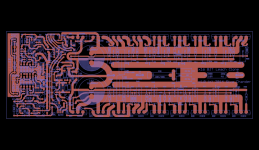
The last published schematic by Jens Rasmussen and a corresponding BoM (which may not match exactly, use with caution after verification). My 8+8 BJT layout, based on the 1.05.12 schematic with some differences, is also attached.
Notes:
1) C4 and C22 do not have a value (I dropped them from my layout as well).
2) R13 and R65 have an incorrect (too low) value. Jens clarified later that they were to be omitted, and I dropped them from my layout (but reused the R13, R65 parts designations for (additional) base stoppers to the drivers).
3) I moved the Zobel network and clamp diodes in-board of the output inductor (IMHO, clamp diodes on the speaker terminals serve no useful function - they're meant to protect the output transistors, not the speakers).
4) All fuses omitted (they should be on the external PSU board instead, a la Sherbourn/Emotiva as well as the original Marshall Leach implementation. Jens probably moved them to the amplifier board because he included large PSU caps on the amp boards also, like I did. IMHO, the fuses can be off-board).
Some other minor changes (mainly transistor types and values of some film caps) have been implemented.
Attachments
Last edited:
Fuses are generally at the source end of the cable supplying power to some client circuit.
Thanks, that's consistent with my suggested wiring: PSU board with fuses, supplying power to (multiple) amp boards.
The last published schematic by Jens Rasmussen and a corresponding BoM (which may not match exactly, use with caution after verification). My 8+8 BJT layout, based on the 1.05.12 schematic with some differences, is also attached ...
It looks like you have done a nice layout. Will you be making the project files and/ or gerbers available?
I just realized that this must be the PCB that you are offering here ...
http://www.diyaudio.com/forums/group-buys/251379-gb-leach-low-tim-8-8-bjt-outputs-bare-pcb.html
Some times I can be slow on the 'take up'. Ha, ha ...
Last edited:
I just realized that this must be the PCB that you are offering here ...
http://www.diyaudio.com/forums/group-buys/251379-gb-leach-low-tim-8-8-bjt-outputs-bare-pcb.html
Yup, that's the one - the first round of 16 boards is spoken for, but I'll do another batch to take care of requests between now and the 28th - that batch will hopefully be ready before mid-March.
Thanks for the replies. Some good info and good ideas but I still have some questions remaining. As per the SOAR circuit... I've got a good chunk of (re)reading done on the Sloan book I have and studied Leach's write up and I think I will modify this aspect to match Sloan's writings. Leach's although probably perfectly protects the OPS 99.9% of the time doesn't appear to protect against highly reactive loads. I design my own speakers and though I do keep a watchful eye on impedance and phase, trial crossovers are sometimes a rats nest and I'd hate to smoke the OPS because of a wiring error or an alligator clip that fell off. Though thats an easy fix.
Was still wondering about rail voltage, as I'm still considering the 50V transformer to give me ~ +/-70V rails. Seems completely do-able component selection wise but some of the traces on the PCB look pretty close to be using those voltages. Anyone have any insight on this? Second I still haven't figured out if this board requires dual supplies or is designed that is 'can' use dual supplied or supply the front end from the main rails... or requires both. OK well I know it doesn't require both to operate but what is optimal?
thanks again,
Ryan
Last edited:
- Home
- Group Buys
- Jens Rasmussen Leach clone group buy