Roger57,
Please post your FFT results when you have them. That would be really
interesting to see. Thank you for your comments and measurements,
both for you tube amp and the Aleph-J.
I haven't read anything about the H2 to H3 transition of the Aleph-J before.
I wonder what mechanism comes into play here?
Cheers,
Dennis
Sure, I'll do further testing over the weekend and do some FFT's at various bias current and power output levels and post the results.
You might want to check out NP's article which covers cause and effect of distortion.
https://passlabs.com/articles/audio-distortion-and-feedback
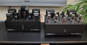
Find attached a picture of one of the amplifier pairs (each has separate power supply) At some point I'll get a full build description, schematics, etc and more pictures on my website...when I get that up and running, hopefully in the next few weeks.
Thread moderator: Will not do any more off-topic posts, in keeping with the rules of the thread.

Attachments
Thread moderator: Will not do any more off-topic posts, in keeping with the rules of the thread.
Pussy. (the DIY workbench looks nice)
Pussy. (the DIY workbench looks nice)
Can't afford to be a rebel. I don't have the friends (or the respect) that you do JV...

I could have answered your other question but missed it. Regarding bias, and as Jim pointed out in his original build guide, there is an advantage to higher bias, to a point. The distortion does improve, and substantially, but at the cost of power dissipation. If you're running 24V rails, just 75mV more across source resistors (i.e., 475mV vs 400mV) results in about 15 additional watts of dissipation. Might not seem like much...but almost 20%.
Thx for reply.
I'm curious as to how you shorted your input - you say you connect "-" to ground...to which ground specifically?
2 questions:
To which procedure are you referring when you say AC bias? The ACS? As in this page?
http://www.diyaudio.com/forums/pass-labs/51808-more-aleph-2-questions.html
If these distortion measurements are about right, what's the point of adjusting AC bias?
http://www.diyaudio.com/forums/pass-labs/38033-proper-current-source-adjustment.html#post438837
OK, they both refer to setting AC bias. So the adjustment of AC bias, although it may result in higher distortion, is based upon a listener's perspective, and little to do with an FFT or analyzer. I suppose this goes back to NP's mantra of not using measurements, but subjective perception.
So, I have it on my bench. The next step to build it into the chassis (actually, 2 of them) and listen. According to everyone that's listened to it, it seems to be the only path of the righteous children of the gate-charged FET.

I'm totally a tube-head, so it will be interesting to see how these Alephs go up against the Class A tube amplifiers. One thing for certain, my power bill should drop.
Thx for reply.
I'm curious as to how you shorted your input - you say you connect "-" to ground...to which ground specifically?
I think you're asking about two different things?
1:
With regards to the "-" input (used for differential) this should be at GND if you are single ended (using RCA). If not on the build guide from 6L6, it's somewhere on one of this thread's pages.
2:
When adjusting offset and/or bias (they affect each other) the "+" input should be (ideally) to GND with a jumper. Although unlikely, leaving it open could make a difference in those adjustments, and I think this could be the case depend on build and ground layout. I usually ground it when setting any amplifier's bias and offset.
In any "commercial" amplifiers I have worked on, the service manual's output bias procedure typically specifies using a shorting plug on the amplifier RCA or differential inputs.
Hope that helps.
If not on the build guide from 6L6, it's somewhere on one of this thread's pages.
I think it's mentioned in the text, but positive it's in a few photos -
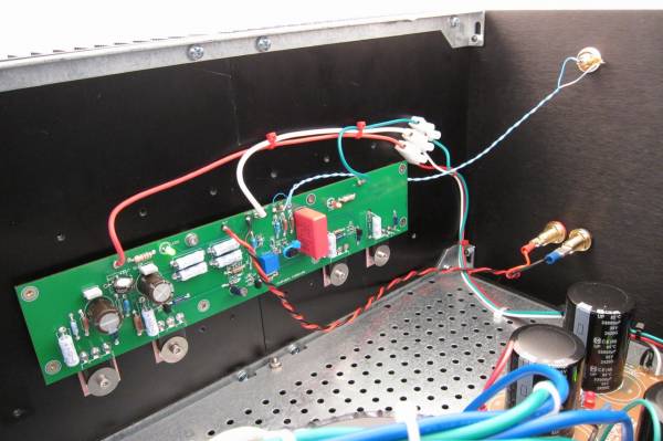
You can see the little, thin blue wire from -in to gnd.
Can I use Grade A JFETs from the store with the Aleph J without modifications?
Also bought A grade LSJ74's, they are a bit low in Idss at Vgs = 0 (3 to 5 ma). They should be BL grade to get the Idss at the required 8mA of tail current.
You could parallel them...there is a bit of an increased risk of parasitics due to the increase of input capacitance, but adding a stopper could remedy(as recommended in build guide) It's unfortunate that the PCB didn't have parallel connection points for that purpose. Or, maybe someone here has tried paralleling without success? Dunno...
I was under the impression that because the CCS is in the circuit ( Q2, D1, C4, R8) the Idss of the Jfet pair kinda doesn't mater as the CCS will set the operating point...
Can somebody with better knowledge of operation shed some light here? I may be wrong, and/or perhaps a particularly low (or high) value will mess it up...
Can somebody with better knowledge of operation shed some light here? I may be wrong, and/or perhaps a particularly low (or high) value will mess it up...
You may need to adjust the CCS to reduce the current it tries to force into the differential. You want the jfets running a bit below idss. Nice that there is a pot to adjust it.
The other question is does the fet current have the capability to drive the output devices? If an F5T running about 10 mA in the jfets can drive 4 output device pairs, I think that 5 mA fets should be fine for driving 2 output devices.
The other question is does the fet current have the capability to drive the output devices? If an F5T running about 10 mA in the jfets can drive 4 output device pairs, I think that 5 mA fets should be fine for driving 2 output devices.
OK, so it looks like I am better off buying the B grade from the store then, correct?
If you can get them. LS (Linear Systems) was supposed to have them in production by end of 2013 (check youtube video)
The process to make these is costly and difficult...Toshiba had perfected it over the years...now all gone...
If LS goes ahead with production - I expect they are evaluating their early results - it will take them some time to achieve the same efficiencies that Toshiba did.
I'm under the impression that they are already in production. Not sure what else there is to evaluate either since Mr. Pass has given the thumbs up.
I'm under the impression that they are already in production. Not sure what else there is to evaluate either since Mr. Pass has given the thumbs up.
Ok, cool. Last time I checked (about 2 weeks ago) there were none available, so that's excellent they have all grades. So looks like you'll want B or C grade.
When I said evaluate - batch processing for high spec devices in semiconductor manufacturing is not easy. It just takes time to analyze results, and get the control variables in line to ensure wafer yields are sufficient to make the devices a viable item.
- Home
- Amplifiers
- Pass Labs
- Aleph J illustrated build guide