Freecrowder. Basic P.S. 800va 45-0-45 secondary (Antec 8445), 1 bridge + four
10000 caps per channel. Rails run at 65 vdc unloaded. Chassis is home built from
scrap aluminum, sinks from heatsink usa. The chassis was by far the most time
consuming in the build process.
Why only one bridge? With two bridges, one per each secondary winding and filtering caps between positive-negative, positive-negative being separate and forming common ground at the end of the line there are some advantages to be gained.
cheers,
Yes I did pose that question earlier in this forum. I decided to go with what I thought
was a simpler option. Secondaries wired in series creating a centre tap, then paralleled to two bridges, one per channel. Sort of quasi mono setup.
Seems to work fine, at least to me anyway. It is amusing that the area of the build
that has given me the most angst is also the one I didn't purchase a pcb for.
Maybe an indication of where I am on the electronic evolutionary scale.
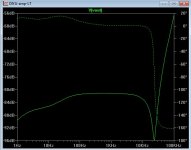
Below1 is Badger PSRR without caps , CRC , anything.
MUCH better than most of the CFA amp projects on the forum , even
with multipliers and CRC's.
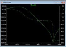
below 2 is with a single supply and a simple CRC (4700u-1R-4700u).")
A single supply CAN be quite good (with this amp/topology)!
OS
MUCH better than most of the CFA amp projects on the forum , even
with multipliers and CRC's.
below 2 is with a single supply and a simple CRC (4700u-1R-4700u).
A single supply CAN be quite good (with this amp/topology)!
OS
Attachments
Honey Badger likes tubes?
BobEllis, you are wise to consider the value of nostalgia in your comparisons. I have a bunch of that to factor in when I listen. It does not make the change in perception due to nostalgia any less real though. We perceive and enjoy, what is the point otherwise?
I just finished a second JFET BOZ using a LDR instead of a pot on the front end, PIO caps instead of Polys. It is nicer but still has the epicurean detail I may, for reasons of nostalgia not be able to handle. It changes everything. It is too lean, too clean. The regular BOZ has more Growl if you know what I mean. I am going to build up a second BOZ with premium parts and see if I can get it to display some more finesse in-between growls
to Freecrowder I say here, here! I have found the combination to provide a bit of both camps. One of my favorite "twin camps" was a Conrad Johnson PV7 in front of some largish commercial PA SS amps driving old OHM Walsh 4s. It was a rocking good system for the workshop. I was less critical then.
I still have a buddy listening to CJ premier 14 as a front end to his Threshold 500s/e. That is wicked good. I am forced to learn to build now with new employment (or lack thereof. That old rocking system is long gone.) and so look to the Honey Badger as a great place to start for a big power amp. Though I would instinctively go first for a tube preamp for the Honey Badger (I have a suitcase full of 6sn7s) I don't know if I can give it the power supply it needs. I don't see the sense of the 12V Aikido but maybe it sounds great, I don't know - it seems too good to be true.
I appreciate your POV. Can you can tell me about mating your Aikido with your A40? It is too bad we all can't get together someplace and check out an Aikido with a Honey Badger.
BobEllis, you are wise to consider the value of nostalgia in your comparisons. I have a bunch of that to factor in when I listen. It does not make the change in perception due to nostalgia any less real though. We perceive and enjoy, what is the point otherwise?
I just finished a second JFET BOZ using a LDR instead of a pot on the front end, PIO caps instead of Polys. It is nicer but still has the epicurean detail I may, for reasons of nostalgia
not be able to handle. It changes everything. It is too lean, too clean. The regular BOZ has more Growl if you know what I mean. I am going to build up a second BOZ with premium parts and see if I can get it to display some more finesse in-between growls to Freecrowder I say here, here! I have found the combination to provide a bit of both camps. One of my favorite "twin camps" was a Conrad Johnson PV7 in front of some largish commercial PA SS amps driving old OHM Walsh 4s. It was a rocking good system for the workshop. I was less critical then.
I still have a buddy listening to CJ premier 14 as a front end to his Threshold 500s/e. That is wicked good. I am forced to learn to build now with new employment (or lack thereof. That old rocking system is long gone.) and so look to the Honey Badger as a great place to start for a big power amp. Though I would instinctively go first for a tube preamp for the Honey Badger (I have a suitcase full of 6sn7s) I don't know if I can give it the power supply it needs. I don't see the sense of the 12V Aikido but maybe it sounds great, I don't know - it seems too good to be true.
I appreciate your POV. Can you can tell me about mating your Aikido with your A40? It is too bad we all can't get together someplace and check out an Aikido with a Honey Badger.
I'd think so. The boards and output devices definitely will fit in 3U 300 mm deep case. Given how little my HB warms up the store 4U case, for reasonable home use 3U will be fine. Transformer and caps may fit. Different manufacturers use different form factors. In my experience Avel Lindberg tends to be shorter and wider than Antek, but check dimensions. With store PSU boards use 35 mm diameter caps and see if you can fit with an extra 8 mm for board and standoffs underneath. Have fun.

As far as tube/SS amplification it all started with a Counterpoint SA 5 and Adcom 555 with Electrostatics. I think the key to my Aikido/A40 is the power supplies. both are way overbilt. The Aikido uses a trafo that came from a small tube power amp and has a tube rectifier. The A40 is a true dual mono down to separate trafos.
they are rated for 600VA each and are CLC designs. Anyway love the Class A design and sound. I will probably use tube/SS forever.
they are rated for 600VA each and are CLC designs. Anyway love the Class A design and sound. I will probably use tube/SS forever.
I was working on my XboSoZ preamp today and remembered someone asked about comparisons with the Badger. I hooked up the Badger and the DX MKIII to my A/B setup. I would defy anyone to tell the difference, at leas through my JBL's. I mean you would think they were clones. I had the volume set the same for both and you couldn't even tell I switched amps. They are both running on +-76v rails.
Blessings, Terry
Blessings, Terry
...The chassis was by far the most time
consuming in the build process.
Chassis usually is.
At least that's been my experience. Great good BTW.Low voltage Honey Badger
greetings all,
I have been reading and rereading this great thread. It really helps to have all of your points of view and experience presented! From them I have come (almost) to the conclusion that I should build a low voltage Honey Badger (32VDC rails) in order to drive very low impedance loads and to "use up" a 132,000uF in 50V caps I have laying around.
I'd use a normally 45-0-45 transformer for this just wire it to use 240VAC in my 120VAC house in order to drop the VAC to 23-0-23. I have tested this to give me the 32VDC rails.
I have also noted the OS is thinking not far off this mark (40VDC rails) for a sub woofer amp so...1). is there a best choice for output devices for this set up?
I believe OS mentioned he'd use the MJE350/340 in his sub woofer amp...2). should any other Q variation be better than another in this low voltage variation?
OS discussed in #589 scaling down R11-13 and 18-19 by a third for his 40VDC...3). should I scale mine to half?
I have plenty of time to plan and plenty of heat sink. I don't need as much power as the HB can develop with 65VDC rails; I just need it to perform with grace under pressure from ill behaved speakers...maybe even sub woofers.
Obviously I can build to 65VDC rails if that is the smart move. I'm looking for the voice of experience
For a sub , use the 340/350 , they are more powerful / have low Ft ..
run em' hot. To go with this "hotter VAS" (56R/11ma/R27) .... get some MJL21193/4's,
with 40v rails .... 2r loads will be easy and safe.
Scale those resisters down at least slightly. The divider just decouples
the CCS's reference from the rail ... many combinations can be used here.
Also... for a sub , omit R24 /jumper C8 .. and just use a single 100pf for C7.
Standard miller compensation is all you need for low frequency use.
It would be good to get at least 40V rails for a sub amp - you might
find the need for that 200W (movies - a party !
) 32V is kind of low ...unless you have one of them DVC 4R's (in parallel)or a 2R driver.
PS - with 65V rails , you can always limit the input signal or lower the
global gain of the amp (R2/3 - R5/6). But you get worse SOA.
OS
Last edited:
I have the NJW3281G/1302G output pairs and MJE15032G/MJE15033G drivers along with the rest of your mouser BOM that you shared with us for v2.4 boards... Can this setup handle 42-0-42 VAC rated transformers with a 4 ohm load? The traffos are fairly large and will not sag all that much (rated at 480 VA per channel).
I have the option of etching my own boards with 4 output pairs per channel which I may do anyway but would the driver stage or anything else need any adjustment in order for this to work for 4 ohm loads?
I already modified the PCB image making it longer and adding an extra output pair. I also modified the power and output traces making them slightly wider. I also modified the silkscreen to use with these changes. I can share with the group if OS and Jason are ok with this. I could also really use an extra pair of eyes to make sure everything is good although I am quite sure it is.
(Just to note that I did want to contribute to the forum and have also bought the v2.4 boards as well as the soft start and DC protect boards.)
I have the NJW3281G/1302G output pairs and MJE15032G/MJE15033G drivers along with the rest of your mouser BOM that you shared with us for v2.4 boards... Can this setup handle 42-0-42 VAC rated transformers with a 4 ohm load? The traffos are fairly large and will not sag all that much (rated at 480 VA per channel).
I have the option of etching my own boards with 4 output pairs per channel which I may do anyway but would the driver stage or anything else need any adjustment in order for this to work for 4 ohm loads?
I already modified the PCB image making it longer and adding an extra output pair. I also modified the power and output traces making them slightly wider. I also modified the silkscreen to use with these changes. I can share with the group if OS and Jason are ok with this. I could also really use an extra pair of eyes to make sure everything is good although I am quite sure it is.
(Just to note that I did want to contribute to the forum and have also bought the v2.4 boards as well as the soft start and DC protect boards.)
You should be OK.
56-58V rails with NJWxxxx at 4R is alright as longas you don't run a constant 110V p-p @ 4R.
Typical music (even techno w/ 303 synth) will not make for "magic smoke".
.. a 20Hz bass signal is 25ms (6+A SOA - 60V)
per device/per cycle. Even with thermal derating (1/3 less SOA-60C),
3 pair NJW can handle the expected 12A load each 25ms cycle.
Bottom line , 3 pair NJW @ <60V might even be able to do 2-3R for those
25ms cycles - continuous (with a large heatsink). Music is not "continuous".
OS
Member
Joined 2009
Paid Member
... This is by far the largest electronic project I have ever undertaken, and I fear has opened the door to more.
Thanks again P.
I would be very afraid - the addiction is powerful
In O.S's 2.4 BOM he has C5 listed as 22uF to 47uF, 63V to 100V.
In his Mouser saved project he has no such capacitor as far as I can tell, but he does have a 22uF 35V that seems to be extra.
Are these what I am supposed to use for both C5 and C9?? Is this 35V cap enough voltage for C5?
In his Mouser saved project he has no such capacitor as far as I can tell, but he does have a 22uF 35V that seems to be extra.
Are these what I am supposed to use for both C5 and C9?? Is this 35V cap enough voltage for C5?
- Home
- Amplifiers
- Solid State
- diyAB Amp The "Honey Badger" build thread