The other day I was searching 01N100D in mouser. By a few clicks I discovered some other interesting depletion mosfet. They are the SIPMOS SM-Signal Transistor, SMD device made by Infineon. One of the most promising one is BSP135 which is available in SOT223 package, 600V, 120mA, but with a discouragingly small power dissipation: 1.8W.
http://www.infineon.com/dgdl/BSP135...c1f67&fileId=db3a30433c1a8752013c1fd4c839399b
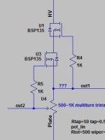
A quick simulation in LTspice reveals that, if we are taking well care of the maximum dissipation(ie Vds x current <=1.8w) this can be a very nice ccs. With only two SMD stopping resistors and two SOT223 on the board, the remaining 500ohm multi-trimmer determines the tiny PCB footprint. And hence a stamp size ccs module can be made with four pins out:
A) High voltage in
B) mu-follower output/out1
C) Anti-triode output/out2
D) connect to the plate/normal CCS output
You don't need to use all the three outputs, either one is good enough.
Ok, here comes the question. I knew some freelance electronic makers in China that may accept order quantity less than few hundreds. If all of these(custom PCB+parts+installation+testing) can be made within $4USD excluding shipping, will anybody interest in a group purchase?
http://www.infineon.com/dgdl/BSP135...c1f67&fileId=db3a30433c1a8752013c1fd4c839399b
A quick simulation in LTspice reveals that, if we are taking well care of the maximum dissipation(ie Vds x current <=1.8w) this can be a very nice ccs. With only two SMD stopping resistors and two SOT223 on the board, the remaining 500ohm multi-trimmer determines the tiny PCB footprint. And hence a stamp size ccs module can be made with four pins out:
A) High voltage in
B) mu-follower output/out1
C) Anti-triode output/out2
D) connect to the plate/normal CCS output
You don't need to use all the three outputs, either one is good enough.
Ok, here comes the question. I knew some freelance electronic makers in China that may accept order quantity less than few hundreds. If all of these(custom PCB+parts+installation+testing) can be made within $4USD excluding shipping, will anybody interest in a group purchase?
Attachments
Last edited:
This is a SMT device that requires proper pad layout for thermal dissipation, otherwise you will not get near that dissipation level witout exceeding the device TJmax.
Thanks, we shall take this into account.
I'd be interested and I'd suggest some gate protection diodes.
ctaudio, for that I am not very familiar. Could you suggest what parameters we shall choose?
I prefer to build my own p2p, but this could be Very useful for retro-fitting existing circuits where space is at a premium.
Yes, that's true. I was thinking if there is market for exotic resistor, fancy coupling cap in re-servicing vintage gears, why not a modularized ccs? a working version with low part counts and costing only few bucks should be attractive.
Anybody look at the capacitance this will have?
C(iss)=98pF, C(oss)=8.5pF C(rss)=3.4pF, typical value when V(GS)=-3V,V(DS)=25V,f=1MHz
These capacitance values are somewhere between the popular 01N100D and DN2540.
For your information:
IXTP 01N100D http://ixapps.ixys.com/DataSheet/98812.pdf
Infineon bsp135 http://www.infineon.com/dgdl/BSP135...c1f67&fileId=db3a30433c1a8752013c1fd4c839399b
Supertex DN2540 http://www.supertex.com/pdf/datasheets/DN2540.pdf
Actually, if PCB foot print is not a problem for you and you are looking for more robust ccs kit set. K&K audio is making a series of kit for DIYers with reasonable price:
K & K Audio - Lundahl Transformers, audio DIY kits and more
You can add a 15v zener between gate and source to protect against exceeding VGS.
Not sure about the zener's polarity, ctaudio can you take a look on this?
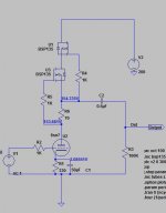
P.S. the original circuit wasn't right, you can't get anti-triode output with that configuration. So revised now, it is still four pins out, A) HV-in, B)P1/out1 C) P2/out2 D) mu-follower out
Attachments
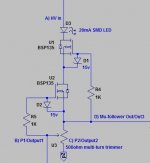
If you don't mind there are some advices.
R4, R5 gate stoppers near (as possible) to gate(s).
Connect R5 "external" pin to "p2" output.
Connect trimmer wafer to "D.)" point (lower FET source).
Connect protection zeners anode to gate stoppers "external" pin.
Maybe the current limiting resistor (for example 10R serial to trimmer) will protecting the CCS, if trimmer value approaching zero.
If you don't mind there are some advices.
R4, R5 gate stoppers near (as possible) to gate(s).
Connect R5 "external" pin to "p2" output.
Connect trimmer wafer to "D.)" point (lower FET source).
Connect protection zeners anode to gate stoppers "external" pin.
Maybe the current limiting resistor (for example 10R serial to trimmer) will protecting the CCS, if trimmer value approaching zero.
Thanks Euro21, of course I treasure your advices.
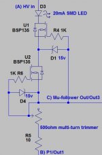
 Hope I am getting you right. It is now three connection points device.
If I am not getting you right, the attached zip file contains a file called proposed circuit. Please share your idea with us. Million thanks!
Attachments
Last edited:
- Status
- This old topic is closed. If you want to reopen this topic, contact a moderator using the "Report Post" button.
- Home
- Amplifiers
- Tubes / Valves
- Will anybody interest in stamp size ccs module?