Oh yes! That's right. The efficiency helps a lot!Could it be my large, efficient speakers?
Remember: The amplifier board power decoupling caps are signal caps, and if they never discharged, the speaker would be silent. Those caps do hi-fi after they recover charge, so we don't want a long wait. The caveat increases corresponding to an increase in power output demand.
To minimize the recovery time, we can use a "divide and conquer" strategy, the active series elements, tandem smaller caps and also dual mono. These enhancements give better odds of getting some or all of the decoupler caps charged full so they can spend less time recharging, more time doing hi-fi.
This sort of caveat (and associated fixes) is not important when listening to the radio with big efficient Tannoy--With the high power demand absent, likewise the problem is also absent.
That high efficiency is not commonplace.
Most of the troubles (and fixes) apply to coping with modern inefficient speakers.
A regulator is needed to protect it (she blows smoke at about 18.5v, so we should use less voltage and disallow voltage surges).What kind of power supply topology would be most appropriate for this amp?
There's several options:
simple psu > simple regulator
simple psu > tracking pre-regulator
CDC psu > tracking pre-regulator
simple psu > capmulti > simple regulator
CLC psu > simple regulator
By adding a filter before the regulator you can "scrape off" the high pitched power noise that the regulator wouldn't notice.
Last edited:
Gilbert Briggs - Wikipedia, the free encyclopediaWay back, high power transitor amps did not exist. Making high power tube amp is no easy task as compare to making efficient speakers those days.
Would you mind telling me where I can find that article please. I found it intriguing. A 60 W amp is "equivalent" to an orchestra of 100 people (estimate)?! I cannot imagine the 60 w amp can deliver the same impact as that when the typamni, the brass instruments and huge drums are going at full force. Could it be the venue that's playing some tricks. Were they simply measuring the SPL at a certain point?
I actually think that amps are getting better and better over the years. Comparing a transistor amp from the 70's to even a "run of the mill" receiver these days will prove my points. Even the remake of vintage design tube amps are sounding better due to better components.
Efficient speakers of the earlier years are mostly horns (speaker make of a single full range driver are quite efficient too). They are efficient no doubt. But not everyone like their sound signature. In comparison, modern day speakers are relatively less efficient due to the type of drivers used and the associated cross-overs needed. However, I personally found that a lot of these "cheap inefficient speakers", such as those from PSB sound quite nice and they can be driven using inexpensive electronics.
Ooops! I think I am way off topics and I better stop here.
Regards,
Here is a mention of the recorded sound vs Live orchestral concerts.
There are images available, they should be out there somewhere.
I have a book here with images and a little more information, and it does mention that the "live" won out, just as it should.
I have a pair of PSB 30 speakers, they were put out by a neighbour because of rotted surrounds. I ordered some new surrounds from China ($10) and glued them in., They do not sound bad, Canadian, eh?
The TI specs. for this amp list the peak output current @ 2amp and the fig. 8 graph shows the max. output current is .77amp @ 18v @ 1% THDOh yes! That's right. The efficiency helps a lot!
TI also mentions that this amp is designed for TV and portable radio applications.
I would suggest that it is only those members with very efficient speakers that are getting the very best out of these little amps, in a hifi sense?
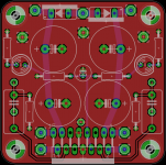
With the help of Daniel I managed to improve the board, and make it smaller at the same time. Should cost little to produce and the design looks real good.
Now, at first I will produce a few boards and if it checks out ok and I like the sound I may consider a group buy. There's still the psu board that I have to finish, I've implemented a tracking pre-regulator into the design but still have to sort some things out.
Meanwhile, a preview of the amp board. It is 5cmx5cm, the input caps are a maximum of 10mm pin distance and also fitted with 5mm pin distance. The power caps are 12.5mm diameter and 5 mm pin distance. I guess you could fit axial input capacitors in there but you'd have to secure them somehow if they are larger. Will check when I get the board.
Attachments
Gilbert Briggs - Wikipedia, the free encyclopedia
Here is a mention of the recorded sound vs Live orchestral concerts.
There are images available, they should be out there somewhere.
I have a book here with images and a little more information, and it does mention that the "live" won out, just as it should.
I have a pair of PSB 30 speakers, they were put out by a neighbour because of rotted surrounds. I ordered some new surrounds from China ($10) and glued them in., They do not sound bad, Canadian, eh?
Thanks! I will dig into that. When I was in university, I spent a lot of time listening to a small pair Wharfdale speakers in my buddy's dorm room. They sound quite nice - until one of the tweeter burnt out

Regards,
No problem, I could just connected some wires in air if need be I will try to sort it out tonight and see what I can come up with. The initial idea was to keep the Signal GND pin in air and connect via a wire to a different GND point on the PCB, but now I have to take the two resistors GND connection into account as well.
I will try to sort it out tonight and see what I can come up with. The initial idea was to keep the Signal GND pin in air and connect via a wire to a different GND point on the PCB, but now I have to take the two resistors GND connection into account as well.I changed my little ebay board to the diode splitter for virtual dual mono and tandem caps arrangement to test drive this. Unfortunately, it got too big to fit in my amp enclosure. Anyway, here's the sound check results:
I tried 330u and 470u, which did do higher resolution, but not so good on tone--fatigue.
I tried 1000u which was higher resolving than stock condition but slightly muddy and a bit lackluster.
And I tried 2200u which didn't differ significantly from stock condition, lower resolving and a bit closed in.
And then I tried 470u||470u||470u, which wasn't significantly different from a solo 1000u.
Next I tried 470u||470u, which works really well for higher resolution, but the amp still needed a touch darker tone to avoid listening fatigue.
Results:
Need tandem caps in the range of 560u~820u
Perhaps, pairs of any of these?
Panasonic FC, "tallboy" versions:
560u EEU-FC1V561 Panasonic | Mouser
680u EEU-FC1V681L Panasonic | Mouser
820u EEU-FC1E821 Panasonic | Mouser
. . . or a fairly lucky choice of larger caps, which may be harder to select.
Are you guys attempting to tailor your amps to suit your own particular speaker/environmental conditions or for an across the board improvement?
I have connected my stock amp to a number of different speakers and what sounds good and not so good is purely based on my personal preferences and application.
I have connected my stock amp to a number of different speakers and what sounds good and not so good is purely based on my personal preferences and application.
I basically want to make a board that fits my system and sounds nice/(er than the Chinese version). As I desoldered the parts from the Chinese board with my desoldering station I managed to rip one trace. It seemed real flimsy and thin. I really don't trust the board. Since I'm a diy guy I figured I'd make a better one keeping in mind some general ideas about board layout vs SQ. Daniel was nice enough to help me with knowledge in this regard.
Also I added some options for testing, like dual rail supply, parallel input capacitors and 5/10mm pin distance for signal capacitors. Since this is a cheap mod (compared to the type of capacitors one could install into any amp) a 4-6$ pcb is really OK. And it also fits the diy spirit perfectly. Off-course, it could sound worse than the original pcb, but I figure I have a pretty good chance of it sounding better. This way I could experiment with different electrolytic sizes/capacitance and input caps. What I'm doing does not guarantee anything for me, but I just try
At the moment I have a M-Audio Fast Track Pro card that I use for USB/SPDIF only, then an AK4396 DAC (kit from ebay, replaced all passives with Dario's BOM), that outputs the signal into a future Aikido ACF2 tube buffer (all diy point to point wiring), then the signal goes into either TA2020 (Muse M20 EX2, replaced ALL passives as well, kept pcb/chip/case), TDA7297 or my tube amp (currently restoring a Sherwood S-5000 II - replaced sockets for transition from 7591 to 7868 tubes, replaced all signal caps with paper in oil caps, tired power resistors and some crusty wires). For speakers I am currently half finished with a pair of Dallas II enclosures for Fostex FE206E 96db SPL speakers
Been a while posting here. I'm still enjoying the 7292 amp. I do have a question and have not been able to find an answer.
The amp is already bridged, but can I parallel them together to get more power(sort of the same idea of paralleling few LM3886s together). i.e. parallel the two outputs spk + to + and spk - to - ? I intend to keep the input caps to isolate both channels' inputs. Of course, datasheet doesn't say anything.
The amp is already bridged, but can I parallel them together to get more power(sort of the same idea of paralleling few LM3886s together). i.e. parallel the two outputs spk + to + and spk - to - ? I intend to keep the input caps to isolate both channels' inputs. Of course, datasheet doesn't say anything.
Also, remember to prank your favorite engineers by mailing them a TDA7297 module.
I mailed one to Keantoken.
What are you suggesting, DIY amplifiers is dead?
Semi dead i guess, it was more of an electronic fashion.DIY amplifiers is dead?
No. Not at all.What are you suggesting, DIY amplifiers is dead?
However, the convenience and practical performance in one little package is astonishing.
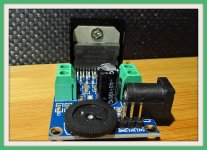
I soldered additional cap to the power supply pins of tda7297 and forgot to check the soldering by multimeter, turn-on the module, a slight 'pop' and then silent.....
A very small solder spill over to the output pin after I used a magnifying glass to check... Lucky I got another one to play around.... If you soldered directly to the pins, please check with multimeter before turn-on
A very small solder spill over to the output pin after I used a magnifying glass to check... Lucky I got another one to play around.... If you soldered directly to the pins, please check with multimeter before turn-on
Gel Flux (petroleum flux) can help prevent accidental solder bridges.
However, generally, your idea is a good one--perhaps a 220u~470u installed parallel with the power jack (or closer to the chip), might improve the imaging. I haven't checked that simpler method yet. There could be some labor choosing models of caps that don't conflict despite one much larger than the other.
However, generally, your idea is a good one--perhaps a 220u~470u installed parallel with the power jack (or closer to the chip), might improve the imaging. I haven't checked that simpler method yet. There could be some labor choosing models of caps that don't conflict despite one much larger than the other.
Last edited:
- Home
- Amplifiers
- Chip Amps
- What the heck? It's less than lunch!