How about air core autotransformer? Wow!
The real high end.
Nah , it would have to be litz type to qualy ......
")
Let's talk a moment about measuring distortion. Typical distortion analyzers of the past went fairly low in distortion residual, perhaps 0.001%, but they did not remove noise from the measurement, AND the measurement bandwidth was typically 80KHz or so. This meant that you got MORE NOISE in the measurement than you could actually hear, and that the NOISE would bury the IMPORTANT distortion artifacts within the noise, keeping us from accurately measuring the actual distortion. This is also a problem with many of today's IC's, the distortion artifacts are buried in the noise even when they might be useful to know about.
What to do?
We had a solution for this, even 40 years ago. We would use wave analyzer (then) or a spectrum analyzer (now) AFTER the first distortion analyzer to separate the harmonics, (to see what the harmonic spread was) and to reduce the noise significantly, because the bandwidth of spectrum analyzer dominated the noise, rather than the spectrum of the initial distortion analyzer. This can relatively get us another 20 dB of resolution. Still this was a problem, because it could be tedious to make individual measurements of all the relevant harmonics and/or it could take (forever) to get the best measurement.
Today, what we use is FFT SIGNAL AVERAGING, as noted in the MAC amp review. This process takes a little while, BUT the noise drops significantly by adding the distortion samples together and dividing them by their number. Like analog magnetic tape width, as you have more samples, the real signal adds directly, but the noise, being random (mostly) tends to cancel somewhat, and you get a rise at the square root of the number of samples instead. This is the method we normally use today. In fact I demonstrated my version of this to Joachim when he was here, 1 week ago. It takes 2 separate analyzers, or a really expensive combined one, but it does work.
This is also a problem with many of today's IC's, the distortion artifacts are buried in the noise even when they might be useful to know about.
Applies to any circuit at some level, nothing special about the little eight legs.
Yes, that qoute ticked me off - I just got the manuscript to that Vol 8 article and I saw the same reference.
Author is Rudolf Moers who wrote that 10 pound book on tube amplifier design
Jan
Jan,
We can’t really expect some modern approach on PSUs.
Everything has been analysed and written during the tube era.
Even about SMPS, albeit then at lower switching rates. Remember the DC to AC conversion through mechanical vibrators?
It is only the magnetic materials available today together with cheap advanced control ICs and robust powerful switching semiconductors that change the implementation scene technicall-wise.
A full article on PSUs, is as good news today as it ever was. That Mr. Moers makes reference to aged sources is IMO to his credit.

George
So the Mac curves are more THD than Noise at the mW level ...?
The excellent distortion spectrum shows otherwise.
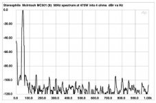
OH, you mean the 15th harmonic is OK?
It is not OK, it is quite poor regarding high harmonics. But, is it an amplifier or an old AP1? Probably an amplifier, at 80% probability, to me.
Anyway, I would like to see a spectrum at 1W and 10W, rather than the 470W one.
Last edited:
Not based on JC's explanation and why so much distortion on that 1st watt....
Can you post a link? You do not mean that THD+N vs. frequency plot, do you.
OH, you mean the 15th harmonic is OK?
You really think you're going to hear that 15th harmonic while listening to virtually any loudspeaker you care to name while it's being slammed with 470 watts?
se
The resistor should be the cable's impedance. It's nothing to do with the speaker nominal impedance.
If you use a very low impedance cable, like 8 ohms, then the resistor will be too much of a load and will get hot. Since the reason for the resistor is to quash high frequency effects outside of hearing, you can just model it as a hf crossover, with the break frequency above 20 Khz.
Because it does essentially does what a transformer does. The core will be the same, but the primary and secondary share a portion of the wind.
jn
Many thanks JN, I asked manufacturer to be sure about hte characteristic impedance of my loudspeaker cables.
Can you post a link? You do not mean that THD+N vs. frequency plot, do you.
Yes ..............
Many thanks JN, I asked manufacturer to be sure about hte characteristic impedance of my loudspeaker cables.
Hope it is not a highend manufacturer. If you measure dimensions like core diameter and distance between wires, we may tell you the characteristic impedance here.
Then I guess we could call a large number of blogers here autoengineer. Really it was more a comment about misuse of a term that be came in to common use much like a variable transformer ( variac) which acts like a tranformer but is not do to the lack the isolation . My question comes from Webster's definition that states as you did that the primary and secondary share windings thus since it the same definition as a transformer this should be a sub class that does not have the galvanic isolation of standard ac transformers that work on magnetic as way of transforming voltage. It is just musing not that much of a question really.The resistor should be the cable's impedance. It's nothing to do with the speaker nominal impedance.
If you use a very low impedance cable, like 8 ohms, then the resistor will be too much of a load and will get hot. Since the reason for the resistor is to quash high frequency effects outside of hearing, you can just model it as a hf crossover, with the break frequency above 20 Khz.
Because it does essentially does what a transformer does. The core will be the same, but the primary and secondary share a portion of the wind.
jn
THD+N vs THD. Discussing the same issue a year ago.
Read the posts in this thread dated 13th and 14th of January 2013
As a good Californian, John believes in recycling.
It's interesting to compare the measurements of the Mac to the Parasound JC1. Not that the imperfections in either of them are anywhere near the threshold of audibility, but you can see why there's resentment shown here for a product that looks, feels, and electrically performs better. Competition is tough.
I'd be happy with either if I were a rich guy who bought equipment instead of designing and building it.
- Status
- Not open for further replies.
- Home
- Member Areas
- The Lounge
- John Curl's Blowtorch preamplifier part II