There is a new program for use with uTracer for model extraction..
Details are here:
The uTracer, a miniature Tube Curve Tracer / Tester.
Details are here:
The uTracer, a miniature Tube Curve Tracer / Tester.
Thanks! we have a winner here - Mr. Reefman has shown a great approach to pentode modeling. Must try it immediately.
Last edited:
ExtractModel 6550A Test 1
Well good news and bad news... First the good news, ExtractModel could be used outside of uTracer - just put the curve capture data file in a space delimited format so they can be read by the program. So far so good...
But the result was a bit strange:
1) the Eg=0V curve was omitted in the plots (not sure if the data were utilized by the program either),
2) the curve fitting was not that close (see left chart below),
3) the Derk model option caused an "invalid integer" error, so the model was generated with the DerkE option.
6550A Test Result - (l) ExtractModel output for Eg2=300V, (r) 6550 SPICE model vs. the Tung-Sol datasheet:
An externally hosted image should be here but it was not working when we last tested it.
Last edited:
Surprisingly, I came across with differences in Vp as great as 10% for the same Ip and Vg !
That doesn't surprise me. 10% is not much, it is what you can get between 2 tubes of the same manufacturer. Transistors can even exibit greater divergences than that. If you want to be sure your model fit your tubes, you have to measure your tubes.
Jazbo8, did you include the required triode curves when you ran the pentode curves? (Also requires a minimum of three sets of pentode curves done at different vs to work correctly)
I have had better luck doing the fitting manually in paint_kip (or asking others better at curve fitting than I) than I have with uT_gui for example and have not yet attempted a run with extract which I will try sometime in the next couple of weeks as time permits.
I have had better luck doing the fitting manually in paint_kip (or asking others better at curve fitting than I) than I have with uT_gui for example and have not yet attempted a run with extract which I will try sometime in the next couple of weeks as time permits.
Jazbo8, did you include the required triode curves when you ran the pentode curves? (Also requires a minimum of three sets of pentode curves done at different vs to work correctly)
Yes, I followed the instruction on uTracer's blog - first just the triode by itself then the pentode and the triode together. Anyway, I only had two sets of pentode curves, perhaps that's it... There is also a small typo in the SPICE code, CG1G1 should be changed to CG1G2 on the PARAMS line.
Also the error code generated by the "P" and "DerkE" settings was "floating-point error - divided by zero" not "invalid integer" as indicated earlier.
Last edited:
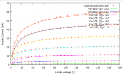
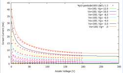
It works, albeit i found an issue when deriving the pentode curves using the pentode/triode curves which Derk is looking at the moment. However, the model can be generated.
here is a sample of the 4P1L pentode curves which I retraced again
Ale
here is a sample of the 4P1L pentode curves which I retraced again
Ale
Attachments
After making a few changes, the SPICE model is matching up well with the datasheet, except for the cutoff region as highlighted in yellow below.
6550A SPICE model (using "B" & "DerkE" settings) vs. the Tung-Sol datasheet:
6550A SPICE model (using "B" & "DerkE" settings) vs. the Tung-Sol datasheet:
An externally hosted image should be here but it was not working when we last tested it.
Last edited:
18040 once again
Jazbo8`s model for 18040 (from post no.122) is very good, say DC measurements.
I was curious to try this old Philips tube designed for Post equipments from 1950`s
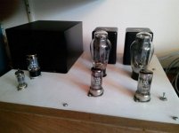
I put Triode wired 18040 instead of C3G as a driver in my SET amp.
-4V (LED bias), 15mA (CCS), anode voltage is 230V one tube, and other 221V.
More than decent replacement for C3G.
Kevin, try them.
Jazbo8`s model for 18040 (from post no.122) is very good, say DC measurements.
I was curious to try this old Philips tube designed for Post equipments from 1950`s
I put Triode wired 18040 instead of C3G as a driver in my SET amp.
-4V (LED bias), 15mA (CCS), anode voltage is 230V one tube, and other 221V.
More than decent replacement for C3G.
Kevin, try them.
Attachments
I've been exchanging some emails with Derk Reefman as a result of my debugging of the ExtractModel tool after testing many pentodes and tetrodes. Derk has kindly updated the tool (currently version 1.032) and hopefully Ronald will release shortly.
Here is an example of the challenging 6e5p russian tetrode. This high-mu tetrode is difficult to approximate with the existing models, and here is a result of the DerkE Beam Model:

It matches really well but with exception of 0V grid voltage curve at higher current values and I guess this is due to the grid current impact.
All bugs found were resolved so far. Recommendation is to plot at least 40 or 50 points within the operating area and also pick 3 or 4 Vg data sets where Vgmax is at least 4 times the Vgmin chosen so help the squares logic fit better according to Derk
I will continue doing some further tests and report.
Here is an example of the challenging 6e5p russian tetrode. This high-mu tetrode is difficult to approximate with the existing models, and here is a result of the DerkE Beam Model:
It matches really well but with exception of 0V grid voltage curve at higher current values and I guess this is due to the grid current impact.
All bugs found were resolved so far. Recommendation is to plot at least 40 or 50 points within the operating area and also pick 3 or 4 Vg data sets where Vgmax is at least 4 times the Vgmin chosen so help the squares logic fit better according to Derk
I will continue doing some further tests and report.
Can somebody find the reason why this model does not work with LTspice ?
.SUBCKT 6P13S-t 1 2 3 ; P G C (Triode) 27-Nov-2007
+ PARAMS: MU= 9.51 EX= 1.26 KG1=686 KP=91.81
+ KVB=8430 VCT=0.00 RGI=1000
+ CCG=18.5P CGP=0.5P CCP=6.5
E1 7 0 VALUE=
+{V(1,3)/KP*LN(1+EXP(KP*(1/MU+(V(2,3)+VCT)/SQRT(KVB+V(1,3)*V(1,3)))))}
RE1 7 0 1G
G1 1 3 VALUE={(PWR(V(7),EX)+PWRS(V(7),EX))/KG1}
RCP 1 3 1G ; TO AVOID FLOATING NODES IN MU-FOLLOWER
C1 2 3 {CCG} ; CATHODE-GRID;
C2 2 1 {CGP} ; GRID-PLATE;
C3 1 3 {CCP} ; CATHODE-PLATE;
D3 5 3 DX ; FOR GRID CURRENT
R1 2 5 {RGI} ; FOR GRID CURRENT
.MODEL DX D(IS=1N RS=1 CJO=10PF TT=1N)
.ENDS
Ofcourse, I know. This is not my point.
There is now 1 ohm resistors at the anode and cathode on purpose and therefore the circuit is a bit absurd, but I mentioned about that.
The situation does not change if these resistors were "correct". There is something wrong with the tube model.
Does it work at Transient and AC Analysis with your computer ?
If so, can you post such .asc ?
24A triode curves
Hello, I usually just lurk the forum and never comment, I´ve used a tonne of information from the forum so I´ll make a small contribution. I´ve traced the old 24A tetrode in triode mode since it is a very plentiful tube and I couldn´t find these curves anywhere, so I´m sure many will find them useful. As a bonus I am also posting the old 47 pentode in triode also, the one I traced was a bit old, so a NOS tubes Gm will be greater and Rp a bit lower. Anyhow, here they are (watch the scale, 24A is in mA and 47 is in A, grid voltages can be seen at the right of the graphs):
Hello, I usually just lurk the forum and never comment, I´ve used a tonne of information from the forum so I´ll make a small contribution. I´ve traced the old 24A tetrode in triode mode since it is a very plentiful tube and I couldn´t find these curves anywhere, so I´m sure many will find them useful. As a bonus I am also posting the old 47 pentode in triode also, the one I traced was a bit old, so a NOS tubes Gm will be greater and Rp a bit lower. Anyhow, here they are (watch the scale, 24A is in mA and 47 is in A, grid voltages can be seen at the right of the graphs):
An externally hosted image should be here but it was not working when we last tested it.
An externally hosted image should be here but it was not working when we last tested it.
- Home
- Amplifiers
- Tubes / Valves
- Vacuum Tube SPICE Models