I've rewritten the CFA vs VFA doc and posted it up on my site - link below.
CFA vs. VFA Amplifiers: a Short Primer
Thanks
") I'm reading...
I'm reading...Hi Kris,
I believe that Paul (mcd99uk) has built the MCP amp, or at least something having a lot in common. As for the Super TIS, this one has not been built yet. No SMDs are required.
Cheers, E.
Yes, all my CFA amps share a lot with the MCP amp. IMHO the CMLC system is significant in it's improvement to sound. Wish more would try it...
Diamond buffer input stage + CMLC + beta enhanced VAS + 2 pole compensation + various output stages = Nice sounding amps.
PS. I'm still digesting your post regarding the calcs and mods for improving the diamond input stage. Don't have enough time for everything I want to build and study.
Last edited:
I've rewritten the CFA vs VFA doc and posted it up on my site - link below.
CFA vs. VFA Amplifiers: a Short Primer
Nice evening read for me
That's generally true for most implementations, but for me the interesting part comes from thinking about why.
High slew rate designs (typically CFA)
The high slew rate capability can be mostly attributed to the combination of a symetrical design and an input stage offering biderectional current-on-demand. Unfortunately the current gain of the VAS is normally severely limited to ensure stability of the VAS idling current, and this results in low open loop gain.
Those attributes and compromises can also be had with a VFA, e.g. using John Curl's preferred topology.
High open loop gain designs (typically VFA)
Here a single-ended VAS is used so it can have high current gain without causing any problems, and this results in high open loop gain. Unfortunately the input stage normally does not offer biderectional current-on-demand, so very high slew rates can't be achieved.
Those attributes and compromises can also be achieved with asymetric CFAs, e.g. by using the Quad303 topology or similar.
Not all amps fall into one of those two categories though. For example, to get the worst of both worlds, go for a symetrical design with a low current gain VAS and an input stage comprising two independent LTPs.
Sure. To get the best of both worlds, use a symetrical topology with the following:
a) An input stage capable of biderectional current-on-demand. (for high slew rate)
b) A push-pull VAS with high current gain. (for high open-loop gain)
c) Common mode feedback to stabilise the VAS quiescent currents.
d) Ideally, the VAS should also provide biderectional current-on-demand without hard crossover distortion, so it doesn't become the weak link.
It's not overly challenging to design something like that, but the CMFB does add some complexity. When I was last home a couple of days ago, I was playing with a proof-of-concept circuit in simulation and there didn't seem to be any problems. When I get back, I'll post a schematic.
In a nutshell, it used a feedback circuit that sets (Ivas1 * Ivas2) = (Iinp1 + Iinp2) * N where:
- Ivas1 and Ivas2 are the collector currents of the two VAS transistors
- Iinp1 and Iinp2 are the output currents from the input stage
- N was about 5 or 10, I forget, but it's easy to adjust.
Hi Godfrey,
These are good thoughts. I'd like to add a couple of points.
First, I prefer push-pull VAS. CFA is a very convenient way to get a push-pull VAS and the advantages it offers.
There are numerous other ways to get a push-pull VAS, including the symmetrical complementary input stage you mentioned as having the potential of the worst of both worlds. There is no need to have a problem with this, and a huge number of very good VFA amplifiers go this way, and of course with a VAS that has good curernt gain. The usual problem of idle current establishment/stabilization can be controlled by common-mode feedback, but also by a simple correction to the arrangement that Randy Slone has in his book. That working arrangement is described in my book.
I usually do a push-pull VAS with a unipolar input stage and a suitable turn-around circuit, such as with a differential pair VAS and a current mirror, as I did in my MOSFET amplifier. Some would compalin about there being more phase lag contribution in that arrangement. I prefer the unipolar input stage because it allows me to use a very good dual monolithic JFET at the front.
Your point about current on demand is a good one. In a CFA, when the demanded current from the input stage exceeds twice the idle current, I think the "other" side of the input stage cuts off and delivers no more transconductance if I am not mistaken.
Also, very high slew rate is achievable with a VFA if Miller Input Compensation is used (MIC). I achieved 300V/us in a 50W amplifier in my MOSFET amp.
Anyway, just a few thoughts, observations and assertions. Comments are always welcome.
Cheers,
Bob
If you mirror and scale the current into the VAS then you get the current on demand property in that section too. That also have the benefit that you have means of controlling the VAS current better as it can thermally compensated in the driving CCS.
Attachments
Last edited:
I've rewritten the CFA vs VFA doc and posted it up on my site - link below.
CFA vs. VFA Amplifiers: a Short Primer
VERY well done literature for the "pitchfork villagers".
Thank you !
To be more clear about the consequences of the added active device ( in LTP ) feedback path, for those who are not familiar to this.
Because the transition frequency of this transistor is not infinite, it will produce phase turn at high frequencies.
Because the original signal and the feedback signal are no more in perfect phase, the subtraction result will not be perfect. The overall gain will begin to increase at HF. This lead to instability as well as increase of distortion. So, we are obliged to compensate with a Miller (or equivalent) to flatten the closed loop, reducing the open loop bandwidth, with no help on distortion...
You will say: Ok, let's use the LTP in inverting configuration. This way, the feedback and the original signals are subtracted passively, no FT, no active device in the feedback path.
That's right. But, then, we face an other problem. Because the base of the inverting transistor present a parasitic capacitance, we need to operate at low feedback impedance for no feedback phase turn because of this RC filter. Too low, in practice, for a usable input impedance in a power amplifier. While, in a CFA, we can make the feedback impedance as low as we want to face the parasitic capacitances of the input transistor emitter, keeping the base input at a nice impedance value.
Yes, CFA at HF is a private club where Murphy has no entrance card.
Hi Esperado,
I think I agree with most of your points here, but it may come down to the numbers.
First, I agree that, all else equal, the difference between CFA and VFA is in the input stage. If we agree on that, then, as you seem to point out, the extra phase lag in the VFA that prevents it from having as high a ULGF comes from the input stage. You are drawing attention to the extra transistor that the VFA has due to its differential pair.
Where I have a little trouble, is how much extra phase lag is actually added by that extra LTP transistor to the path, when both sides of the LTP are terminated in a low impedance (e.g., low impedance feedback network, with a shunt of less than 200 ohms). I am also assuming a perfect current source tail for the LTP without any capacitance to ground.
The combination of the feedback network and the input stage in a CFA or VFA is a transconductance, and it has a frequency response. The transconductance I am talking about is that from the point where the output signal is applied to the feedback resistor to the output current of the input stage. If what you are saying is true, then if we simulate that transconductance for CFA and VFA, we should see the gm for the VFA begin to fall off at a lower frequency than for the CFA. In other words, there is a pole (maybe more than one) in the feedback network/input stage combination).
So the question for me becomes, is that pole(s) close-in enough to make the significant difference in achievable ULGF that we see.
Finally, a related question is whether a JFET input stage in a VFA will be similarly less fast than the input stage of a BJT CFA input stage.
Cheers,
Bob
Waly -- I understand the frustration you have with such vague terms..... I do that to leave the door open as wide as possible for comment. You always want it narrowed down. Its just a hint; It is up to you to pursue the matter. Such as using characteristic curve tracers, data sheets and app notes. [my professional background includes RF/Microwave precision measurements - not audio. My approach is more of a management style... you guys are the experts.]
Thx-RNMarsh
Thx-RNMarsh
Last edited:
Bob, may-i suggest-you to play with the two comparison LTSpice schematics here: www.esperado.fr/fr/temp/compare_vssa/files.zipWhere I have a little trouble, is how much extra phase lag is actually added by that extra LTP transistor to the path, when both sides of the LTP are terminated in a low impedance (e.g., low impedance feedback network, with a shunt of less than 200 ohms). I am also assuming a perfect current source tail for the LTP without any capacitance to ground.
I know a very nice web site where you will find good models. ;-)
BTW: i use to ask the simulator to explore the bandwidth at the base of the VAS transistors: it is full of interest ;-)
And, of course, "may come down to the numbers".. in some configurations...can be very close...
I would be very interested to explore a FET input stage comparison too...if i could reach the same performance (distortion) level with them...
Last edited:
Chapter on CFA being written here --
Looks like we wont need a chapter in DS or BC's book on this subject
THx-RNMarsh
I've rewritten the CFA vs VFA doc and posted it up on my site - link below.
CFA vs. VFA Amplifiers: a Short Primer
Looks like we wont need a chapter in DS or BC's book on this subject
THx-RNMarsh
I would be very interested to explore a FET input stage comparison too...if i could reach the same performance (distortion) level with them...
yes; so would I. It would be very useful to know how they compare. If you choose HF/RF jFET's the C is very small and thus distortion from C will be very small. Such as, 2N5457/2N5460 etc But for power amp the voltage rating by themselves is too low. maybe Ok fro IPS at lower voltage or cascoding with HV bipolar.
Thx-RNMarsh
Last edited:
And, of course, "may come down to the numbers".. in some configurations...can be very close
Mr. Cordell has this outstanding capacity of telling the truth without making it sound offensive for the contenders.
In each and every imaginable configuration, the VFA LTP input stage pole is in the tenths or even hundreds of MHz. This is what also jcx, Mr. Zan, yours truly and others repeated ad nauseum. The effect that Bonsai is reporting (of CFAs having the open loop OPS pole pushed towards higher frequencies) has another explanation: the HF VAS output impedance can be lower for the CFA, compared to a standard VFA. This doesn't mean it can't be made the other way around, if that would really be critical (which is not).
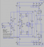
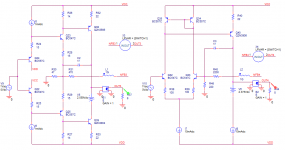
Just replace the output stage with an ideal VCVS of gain 1 and you will note, for all practical purposes, a single pole (from the VAS) for both the CFA and the LTP VFA.
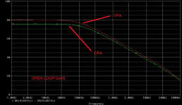
Example is attached, you can clearly see the input stage VFA pole far away at about 50MHz or so. The example is run on Bonsai schematics, no compensation was used.
EDIT1: Added the schematics, for clarity.
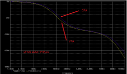
EDIT2: Open loop phase also added. As expected, the VFA LTP pole causes the open loop phase to gap at over 50MHz. Is it now clear that the VFA LTP pole has virtually no impact?
Attachments
Last edited:
I agree on both accounts. I've not found the LTP input pole to be a limiting factor when playing with my VFA.Mr. Cordell has this outstanding capacity of telling the truth without making it sound offensive for the contenders.
In each and every imaginable configuration, the VFA LTP input stage pole is in the tenths or even hundreds of MHz. This is what also jcx, Mr. Zan, yours truly and others repeated ad nauseum.
Please, Waly, if you want to explore and compare, use something more fairly comparable.
You can play with my files: Same open loop gain, same closed loop gain, same VAS, same OPS.
http://www.esperado.fr/temp/compare_vssa/closed-loop-bandwidth.gif
As the only difference is the input stage, can you say it has no influence ?
Yes, Mr Cordel has the outstanding capacity to be both serious, competent, open minded and more than polite and respectful to his interlocutors: nice and friendly.
Last edited:
Please, Waly, if you want to explore and compare, use something more fairly comparable.
I've used your BFF Bonsai examples. If those doesn't cut it for you, I can't further help; in fact, I'm not even sure if you really want or need any further help. You already seem to believe you have the definitive answers.
Anyway I don't currently, and don't plan to learn how to, use the LTSpice free toy.
... When I see SIM'ed circuits using small pfd values for comp, I know they wont work in a wired up circuit with all the strays involved.... so the actual end result is usually lesser and a bunch of trial and error...
Maybe there is less of that with CFA and its low Z circuitry etc....
Fair point that lower Z makes for more convenient values of compensation capacitors. Perhaps that explains the common lore that "CFA" are easier.
But a VFA with comparably low Z feedback resistors should have the same benefits, I expect.
I like such low Z for noise anyway so it's still about even for me.
Best wishes
David
On the models used in the update to my document, the feedback resistors on the VFA were lowered to the same values as the CFA since it was pointed out that this did not allow an apples to apples comparison. It made virtually no difference.
I specifically chose MC to allow easier comparison of the basic properties of the two topologies. As I point out, you can make high OLG CFA's, bu then they morph into VFA like amplifiers with regard to PM - so the ULGF has to be lowered to deal with it, or you have to go to TPC, MIC etc.
I also tried MIC on the VFA, but did not include the results - the doc is already 24 pages long. The results were not substantially different.
The Zout drops with frequency on MC - so the OPS is being driven from a lower Z at HF. As I note, beyond the IPS, both amplifiers are very similar.
I doubt, and don't expect, that the doc will be all things to all people. As I have repeated many times, I am not fixated on any specific topology and I hope the doc reflects that.
BTW thanks for the positive comments.
Last edited:
- Home
- Amplifiers
- Solid State
- CFA Topology Audio Amplifiers