My "base misconception" is just transmission line theory, as found in any decent textbook. If you don't accept that then we have no basis for useful discussion. You now appear to be admitting that your claim is irrelevant to audio as it involves frequencies well outside the audible band.
I have tried on several occasions to understand what you are saying. I have sought to check if there is any relevance in it, by first establishing that I have understood what you are saying. My conclusion is that bouncing fast pulses or sharp edges up and down a transmission line is irrelevant to audio (as I first suspected). The behaviour of a cable at audio frequencies is well understood (although clearly not by everyone).
As far as I am concerned this discussion is now closed. For the avoidance of doubt, I am not backing down. I maintain my position, but I cannot convince you. Maybe someone else can try?
I think you are the one that needs to think about the system level behaviour here, there is a combination of things happening that provide a plausible reason for cable differences that JN has put forward.
1) the ear is extraordinarily sensitive to time delays between differnt parts of the sounds/music arriving from the speaker because of evolutionary pressure brought on by apex predators along the way.
2) the short line is not matched between either the amplifier or the loudspeaker in the AUDIO band.
3) the telegrapher equation tells us that the risetime and delay for each note in the audio will be different both due to the different match between cable and load, and due to the different fractions of a wavelength.
4) the difference in delay between the 300Hz portion and the 10KHz portion of a wavefront will change the apparent image percieved by the listener compared to the image that would be felt when a cable with perfect impedance matching is used.
this combination of issues makes it plausible that cables with a very high or very low impedance will show imaging changes compared to a better matched cable. Scott shows he also gets it, and is preparing to try and see if the apparent image for sound can be changed with a cable change on one side only to exagerate the effect. JN has also stated that he is unsure if it percievable but the sums so far make the changed noted within the limits of human perception and not outside those limits.
Last edited:
I guess you guys are referring to Kanye West winning his case against Coinye yesterday?
Coinye - Wikipedia, the free encyclopedia
http://coinyeco.in/
Coinye - Wikipedia, the free encyclopedia
http://coinyeco.in/
Attachments

Last edited:
For those asking about liniarty of pur optical system, the SFDR for the system is about 115.
We're not talking about pure optical it's volts in volts out. Long haul telecom specs need lots of translation to 20Hz-20kHz audio. For another thing the 1/f noise corner on a lot of high GHz components is horrible.
By and large fiber transmission of high bit rate digital audio would be the route today. Bit perfect absurdly low jitter links can be achieved by applying normal engineering principles.
I guess you guys are referring to Kanye West winning his case against Coinye yesterday?
Coinye - Wikipedia, the free encyclopedia
http://coinyeco.in/
I guess you don't get out much.
Congrats and with all that traveling not one person who did an A/B test of the same cable makeup..")
You did? Careful control of length R, L, and C?
BTW Bateman's 4.9 meter cable was about .1 Ohm so that's about 1dB in any region the speakers are 1 Ohm. A bets are off there, asking for no peeking is one thing equalized and level matched is just too much I think. Will never happen.
It would be interesting to compare. Not electrical connections between components goes a long way.
My amps don't have a light input, we are not fully comunicating here. I don't see how fiber optic sensors (Bragg scattering, etc.) apply here at all.
Last edited:
You send the preamp analog signal to the amp. All in the analog domain. If you all do a cable shootout, I would like to have you compare my old line level pair. 20 year old technology. I am just trying to convey the technology has really advanced since then. Maybe end the cable argument?
Most passive crossovers will do way more of this type of damage than a few meters long audio frequency transmission line.I think you are the one that needs to think about the system level behaviour here, there is a combination of things happening that provide a plausible reason for cable differences that JN has put forward.
[...............................]
4) the difference in delay between the 300Hz portion and the 10KHz portion of a wavefront will change the apparent image percieved by the listener compared to the image that would be felt when a cable with perfect impedance matching is used.
[.........................]
You did? Careful control of length R, L, and C?
No, but same cable make up , length, twist, dielectric, cover , I usually measure afterwards and compare subjective notes. We also did experiments wiring xover in pure silver, then compared TF, i cant recall now what the difference was vs copper when measured, if any, subjectively there was a difference our panel of listeners did not like the brightness of the silver over copper in the xover, they were not aware of what was what or what we were doing , just asked to give their subjective evaluation....
Are you going to put a pre together ....?
I think you are the one that needs to think about the system level behaviour here, there is a combination of things happening that provide a plausible reason for cable differences that JN has put forward.
1) the ear is extraordinarily sensitive to time delays between differnt parts of the sounds/music arriving from the speaker because of evolutionary pressure brought on by apex predators along the way.
2) the short line is not matched between either the amplifier or the loudspeaker in the AUDIO band.
3) the telegrapher equation tells us that the risetime and delay for each note in the audio will be different both due to the different match between cable and load, and due to the different fractions of a wavelength.
4) the difference in delay between the 300Hz portion and the 10KHz portion of a wavefront will change the apparent image percieved by the listener compared to the image that would be felt when a cable with perfect impedance matching is used.
this combination of issues makes it plausible that cables with a very high or very low impedance will show imaging changes compared to a better matched cable. Scott shows he also gets it, and is preparing to try and see if the apparent image for sound can be changed with a cable change on one side only to exagerate the effect. JN has also stated that he is unsure if it percievable but the sums so far make the changed noted within the limits of human perception and not outside those limits.
All these things are irrelevant when confronted against "room effect"...(well ... talking about "system level behaviour")
Just move a chair near the "sweet spot" and you probably will be able to listen a big sound change... at least a bigger one than the pretended "wire effect"
May be worthwhile re-mentioning that part of the progression towards optimum sound is the steady disappearance of the "sweet spot" - meaning, that the "best" sound is no longer heard in a prescribed place, it occurs everywhere. The "sweet spot" becomes anywhere in the room, if you sit in the conventional position for such there will be no perceptible difference, there, as compared to anywhere else ...
Then one must use radial speakersMay be worthwhile re-mentioning that part of the progression towards optimum sound is the steady disappearance of the "sweet spot" - meaning, that the "best" sound is no longer heard in a prescribed place, it occurs everywhere. The "sweet spot" becomes anywhere in the room, if you sit in the conventional position for such there will be no perceptible difference, there, as compared to anywhere else ...
(i.e. Walsh type)
No, not necessary. Conventional radiators will work this "trick" but the sound coming from them has to be extremely clean. Otherwise, the distortion artifacts give away too many clues, subconsciously, as to the location of the drivers, and this "illusion" won't manifest ...Then one must use radial speakers
(i.e. Walsh type)
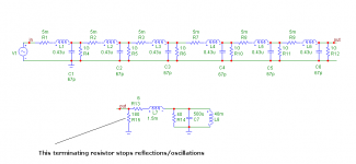
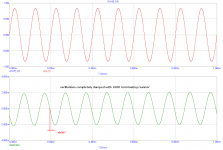
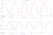
This is what we get as early reflections. These reflections are caused by sudden turn-on of the sine wave in the voltage zero. This turn-on has infinite spectrum, so it excites reflections/oscillations that disappear after some time.
This is similar to so called 'first cycle distortion', similar misconception.
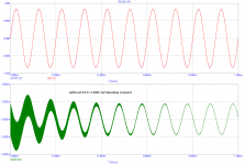
I have tried a simple termination with 180 ohm resistor at the end of the lumped circuit model. All the oscillations/reflections have disappeared, see images.
I have also tried a model based on telegraph equations only, still not sure what to think about (no images shown re this model).
Attachments
The "shift" is frequency dependent and initial transient (turn-on) dependent. It also grossly depends on speaker+crossover lumped impedance, and cable lumped elements impedances.
The effect of the additional terminating resistor is easily measurable as a decrease of RFI interference amplitude on the cable and speaker terminals.
The effect of the additional terminating resistor is easily measurable as a decrease of RFI interference amplitude on the cable and speaker terminals.
Attachments
Last edited:
- Status
- Not open for further replies.
- Home
- Member Areas
- The Lounge
- John Curl's Blowtorch preamplifier part II