Later in the mid 90's I introduced an analog fiber optic transceiver pair. I had one distributor tell me the thing works better than any cable, but cable amount to the majority of advertising revenue.
Are you talking volts to light and back again? What kind of THD/SNR could be maintained.
What other measurements have you conducted other than measuring resistance?No, there is no difference between silver and copper cables of the same construction, other than a small decrease in resistance for silver
What do you think of an opposite opinion that in a better system any small change will tend to be more audible than in a worse system?In fact I would worry if a cable caused an audible difference, my concern being that either the cable is not engineered properly for the job or the electronics are so badly designed that a cable can cause a difference.
Is that because they are measured differently? What measurement differences have you found?As to aluminium cables, I only see them for power distribution and would not use them for audio
I will state my position again, which I believe to be the established science as found in the EM textbooks: if you carry out a full wave calculation/simulation at audio frequencies on a short transmission line with an unmatched termination then the result you will get is identical to that obtained from the corresponding lumped calculation. This is what I have been stating, and this is what you have been disputing. I am unclear whether you accept that this is what you are disputing.
I don't think he disputes it, at least I don't think so. At this point I don't know why there is any argument.
.......... The basic measurement problem is trying to get accurate zero crossing numbers at the single digit microsecond level with 500hz to 5khz sines..........
What would be the problem?
Shooting from the hip, I would bet it behaves like an analog to the Gibbs effect.
Which implies there is a discontinuity. Where is it?
Jn made a remark which seems relevant
Two notes on your model. You included an inductive discontinuity, hence the ringing.
At the sim screenshots
http://www.diyaudio.com/forums/attachments/lounge/392670d1389293146-john-curls-blowtorch-preamplifier-part-ii-tline.jpg
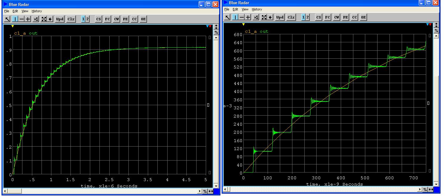
the staircase time step is ~75ns. What does this time interval represent in this sim experiment?
George
The fiber cables used a couple of tricks the almost every EE would miss and they did make a difference.
Well, what are the "tricks" that almost every EE would miss??
Cyril goes to some length detailing how to make/modify a bridge such that it was capable of doing so.Isn't this rf bridge intended for range 100kHz and above?? How about "accuracy" of such measurement at 10kHz?
8721A Directional Bridge, 100 kHz to 100 MHz [Obsolete] | Agilent
It is the only 8721A bridge I found..
You again state the obvious. Actually, you repeat what was stated by me, simply regurgitated. Go back and read again. I stated to df96 that the cable ws 2000 meters too short for a 4 uSec reflection.10kHz wave length is 30km (30 000m). The speaker cable in question has length of some 2m. There is no way to apply transmission line reflections of 30km wavelength on 2 meters of cable (1/15000 of wavelength).
Please do yourself a favor. Sit back and learn before posting blindly on a topic.
No.P.S. I only hope you do not speak about instant turn-on of the sine wave, that has spectrum spread to infinity.
I like your quantization statement. I encountered that about 12 years ago when I was doing transient analysis of biwiring.Shooting from the hip, I would bet it behaves like an analog to the Gibbs effect.
Next is a response to my statement (following).
The basic measurement problem is trying to get accurate zero crossing numbers at the single digit microsecond level with 500hz to 5khz sines......
Accuracy. It's not very easy discerning the time delay between two 500 hz waveforms at the 1 uSec level. When the timebase is 2 or 5 uSec, the 500 hz signal is kinda flat. In addition, the resistor being used for measuring current will have a terminal voltage which is the sum of the current times it's resistance, and the rate of change of the current times it's inductance. The second term is 90 degrees out of phase with the IR drop, so will contribute to error in discerning any delay.What would be the problem?
jn
It represents two transits of the signal, from the source to the load, and from the load to the source.At the sim screenshots
http://www.diyaudio.com/forums/attachments/lounge/392670d1389293146-john-curls-blowtorch-preamplifier-part-ii-tline.jpg
the staircase time step is ~75ns. What does this time interval represent in this sim experiment?
George
If you look at the very first step, it is roughly 35 nSec after zero. that is the transit time through the cable length.
The step encounters the load, reflects inverted back to the source. At the source, it reflects inverted again and heads to the load. That takes two transits, or 75 nSec. All subsequent steps in the view shown will be 75 nSec apart.
As time goes on, the leading edge will continue to decrease slope and the steps will become indistinguishable from a smooth exponential rise. Also, as time goes on, the lower frequency content of the step will dominate, and the tail of the rise will slow down more than the LC prediction due to the cable impedance rise and it's slower prop speed. At this time however, the signal will be so close to 100% that the difference will be miniscule.
jn
You guys are catching ghosts and should check your test methods. Anyone else than Bateman measured 10kHz reflections on 2m cable? I would like to see REAL results (with proper instruments designed to measure 10kHz waves, not >1MHz waves).
I will elaborate a tad more, as I do like and am in awe of your work.
Take a look at scott's simulation. Note that it is a view from the load. In other words, what is being displayed is the signal that is travelling at prop velocity Towards the load.
Now, think about what the signal is doing in his sim.. It is travelling back and forth through the cable.
The RF bridge is seeing the signal which is travelling towards the SOURCE. It's there, it is a staircase rise, it is 35 nSec ahead of the load waveform, but it is indeed heading to the source.
That is what cyril measured and displayed. We can't see any steps in the waveform because the slope of the 10Khz wave is way too slow. Think of scotts sim with the leading edge slope very small.
jn
It is frustrating at times, as the physicists I work with understood this in a relatively short time...minutes.Despite how it may appear to you, I am trying to understand what was written.
Granted, on forum is never a good way to transfer knowledge.
Again with the internet canned arguments. And you claim surprise??The misconception is yours, in believing that the result from the two different calculation methods could be different.
I will ignore your comments about my supposed ignorance.
They are meant to point out how you are coming across. I didn't know how to express it in a better fashion.
Here's your base misconception in a nutshell. I've held off explaining this to you, as I had hoped you would eventually figure it out on your own. I just gave that up..At audio frequencies the line impedance becomes not only high but also reactive
We are looking at and discussion settling times and delays in the 1 to say, 10 microsecond frequency range. Invert that timeframe and tell me where the audio frequency is??? Haven't you ever bought a tectronix scope probe??
The most difficult aspect of this problem is the concern over 5 uSec level effects in a signal pair which is typically 20Khz max.
The balance of your post is irrelevant. Stop claiming what my position is, as you continue to mis-state it.
jn
This is what we get as early reflections. These reflections are caused by sudden turn-on of the sine wave in the voltage zero. This turn-on has infinite spectrum, so it excites reflections/oscillations that disappear after some time.
This is similar to so called 'first cycle distortion', similar misconception.
Does this distortion vary with wire size/type ..?
No, there is no difference between silver and copper cables of the same construction, other than a small decrease in resistance for silver, and I can not determine any difference in sound of such cables. In fact I would worry if a cable caused an audible difference, my concern being that either the cable is not engineered properly for the job or the electronics are so badly designed that a cable can cause a difference. With analogue I do agree that in certain circumstances there can be some interaction that may cause a change to the waveform thus causing a measurable change, but again this would be measurable, for digital transmission the correct cable will not cause any subtle changes, if it doesn't work it will be very noticeable (I will not include noise pick up as this is a separate subject and involves a whole system for assessment).
As to aluminium cables, I only see them for power distribution and would not use them for audio/digital etc.
There's a big difference sonically between silver and copper , one would have to be tone deaf not to notice ...
The usual lcr
I have heard differences (or thought I have heard differences) with changes to my system (things have also sounded different though due to my mood and other factors), so I am rather cynical and do not trust my ears as much as others do, and like some empirical back up, and a solid explanation of what is going on.
")
Yes.What do you think of an opposite opinion that in a better system any small change will tend to be more audible than in a worse system?
I have heard differences (or thought I have heard differences) with changes to my system (things have also sounded different though due to my mood and other factors), so I am rather cynical and do not trust my ears as much as others do, and like some empirical back up, and a solid explanation of what is going on.
Does this distortion vary with wire size/type ..?
The so called 'first cycle distortion' in amplifiers is not a non-linear distortion. It is a linear phenomenon and depends on BW (high frequency corner) of the amplifier.
Regarding wire reflections, they depend on length and rt(L/C), or more complex rt((R+jwL)/(G+jwC))
Really, can you point me to a supplier/PN of this silver wire that you hold in such a high regard? I like to read what the mfg has to say about their product and it application.There's a big difference sonically between silver and copper , one would have to be tone deaf not to notice ...
Complete Ag, solid or stranded?
If it is such a big difference, can you also point me to a method to measure this sonic difference? or only ears/brains/you can tell this difference?
Show of hands, who else can state the same? Maybe, also what brand of Q-tips you use.
Sorry, I find it a hilarious discussion of nonsense and a change from writing code for my radio project.There ya go, 2 for Ag. and now we throw in a Cu/Al mix into the equation too, hum a supplier as well?
Last edited:
The discontinuity is at the start of the wave.
Actually, I asked about a physical discontinuity modeled as an inductor. You are accurate in that the signal discontinuity is at the start of the wave, and it is the reason for the ringing response. The problem I speak of is, the ringing states that the load is unable to draw current fast enough to prevent the signal from overshooting...a consequence of inductance somewhere in the path.
I had this issue back in 1981 when I was using a 1 ohm BeO microwave resistor in a TRR setup. While the resistor was indeed capable of 10 Ghz operation, that performance required the resistor be used such that the return current went coaxially outside the resistor; the resistor was cylindrical. Any attempt to return the current via a wire close to the resistor body caused overshoots when the current rise was 4 amps/nanosecond. The diode in series with the resistor would therefore be current starved when I needed it most.
By converting to 10 pieces of 10 ohm units, and arranging them on a ground plane in a spoked arrangement, I was able to get the parasitic L out, and the subsequent 250 picosecond risetime was flat topped.
Scott's sim demonstrates the exact symptom I had with real hardware, so I asked why the sim had that in.
With no inductive element built into the model, we are stuck with guessing as to why the model exhibits such behavior. Since the ringing and damping appears to be correlated to the slew rate of the jumps, I suspect it may be a simple math artifact as well.
jn
Agreed. In addition, for this specific system the source and load impedance are very important as well.Regarding wire reflections, they depend on length and rt(L/C), or more complex rt((R+jwL)/(G+jwC))
jn
There ya go, 2 for Ag. and now we throw in a Cu/Al mix into the equation too, hum a supplier as well?
I bet 4 quatloos on gold..
An additional 2 quatloos to anybody who finds the incorrect word I used.
jn
Last edited:
- Status
- Not open for further replies.
- Home
- Member Areas
- The Lounge
- John Curl's Blowtorch preamplifier part II