I am also curious, at very small portions of a wavelength is it sufficient to measure L/C and compute Z? BTW I get ~.0025 Ohms/ft R if that picture is 4-1/2" stripes in parallel. Folks have tried 6-RG58 in parallel go for 50?
Nope. It is insufficient.
As I said to DF96, it provides the lower bounds for Z as well as the upper bound for prop velocity.
A simple scaling factor of 2 to 4 gets us into the audio freq Z and V.
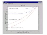
I would have just posted the L and C curves, but I couldn't find them immediately. The z graph basically showed what was necessary for the discussion.
edit: The left pic is of the 4 conductor Valhalla clone, but the graph is actually of a two strip construct.
I did the same basic thing using a 1/2 inch wide flat copper braid. Readings were consistent with what I posted. I did the braid because the copper strip has a tendency to buckle when I make an 8 ohm cable. As the cable is bent, the inner foil will tend to buckle and the outer will try to stretch. Using braid allows the conductor to flex, so it won't buckle.
jn
Last edited:
http://www.diyaudio.com/forums/multi-way/124824-electrolytics-sound-fine-3.html
Start with post 62. This was with electrolytics; polymer dielectrics have more linear polarizability.
Thank you for the work. Not an exhaustive test but adequate for testing the claim.
Re elcaps, I find auplater’s posts of importance.
And here are two classic lines from SY
drink and Salas madI get mocked all the time. Shrug. It doesn't change anything in my life, this is just a hobby.
For helping out just one, it is better to entertain a 1000 for free, in my book.
George
Nope. It is insufficient.
As I said to DF96, it provides the lower bounds for Z as well as the upper bound for prop velocity.
jn
I have not fiddled these details for a while, nice review here. Coaxial Cable Characteristic Impedance vs Frequency I guess the paralled T lines never worked out at audio.
I have not fiddled these details for a while, nice review here. Coaxial Cable Characteristic Impedance vs Frequency I guess the paralled T lines never worked out at audio.
Interesting link, thanks.
Note that they used the skin depth approximation equation, which is inaccurate for round conductors when the depth is more than say, 5 or 10% of the conductor radius. They are off by about a factor of 3..
I wonder what other approximations they used which are not close.
jn
I wonder what other approximations they used which are not close.
jn
Are you familiar with Schelkunoff, 1934 (look out Bessel functions)? I would assume they would not publish data that was 3X off if they have the exact derivation to compare. Oh well back to the little 8-legs for me.
OK, that explains it. It is not the characteristic impedance of that cable, but the characteristic impedance of a theoretical cable with the same L and C but no resistance and perfect insulation. I'm not sure there is a short name for that.jneutron said:The graph is simply z = sqr(L/C). As such, it ignores the distributed R and G.
Yes, L and C can store energy.As measurement of energy storage within the cable at audio frequencies, it is enough information.
If you grounded one side and put a voltage on the other side then it would act as a very short folded monopole. Its radiation impedance as an antenna (x4, as it is folded) will appear in parallel with its impedance as a transmission line. Given that it is about 1% of a quarter-wave in the 100kHz region I would not expect this to make much difference. However, if it was coiled up then there could be an effect as the antenna mode (i.e. common-mode) would then have a 'loading coil'.It is a roughly 10 foot long two conductor system with 1.5 inch spacing. Because the capacitance was very low, I would not expect a bulk resonance at 200Khz, and the line length is also too short for resonance via t-line reflections. So as I stated, I believe it may have been broadcasting.
Let me rethink a little.
The wide flat geometry could mean that the antenna-mode impedance (mainly capacitive) is much lower than usual, while the 'end-on' positioning will mean a higher than usual transmission-line impedance. This means that they could interact at a lower frequency than might be expected for 10' of cable. The effect would be a rise in impedance as the capacitive antenna is in parallel with the inductive (shorted) cable.
The wide flat geometry could mean that the antenna-mode impedance (mainly capacitive) is much lower than usual, while the 'end-on' positioning will mean a higher than usual transmission-line impedance. This means that they could interact at a lower frequency than might be expected for 10' of cable. The effect would be a rise in impedance as the capacitive antenna is in parallel with the inductive (shorted) cable.
Superconducting vacuum insulation stripline.OK, that explains it. It is not the characteristic impedance of that cable, but the characteristic impedance of a theoretical cable with the same L and C but no resistance and perfect insulation. I'm not sure there is a short name for that.
As I said, it provides the lower limit on the cable's impedance, and the upper limit on it's prop velocity. And for audio, it's about a factor of 2 to 4 off.
You restate the obvious.Yes, L and C can store energy.
That energy storage is the reason a sub wavelength t-line with very low impedances at either end has a settling time 3 orders of magnitude slower than a matched system.
If you grounded one side and put a voltage on the other side then it would act as a very short folded monopole. Its radiation impedance as an antenna (x4, as it is folded) will appear in parallel with its impedance as a transmission line. Given that it is about 1% of a quarter-wave in the 100kHz region I would not expect this to make much difference. However, if it was coiled up then there could be an effect as the antenna mode (i.e. common-mode) would then have a 'loading coil'.
While connecting it in wild and wonderful ways may be of interest, I just did a standard inductance measurement. It required shorting the far end. It was not coiled, but straight, and on a granite table.
jn
Last edited:
At 1nSec per foot, a gig is one foot wavelength. 100 meg is 10 feet,Let me rethink a little.
The wide flat geometry could mean that the antenna-mode impedance (mainly capacitive) is much lower than usual, while the 'end-on' positioning will mean a higher than usual transmission-line impedance. This means that they could interact at a lower frequency than might be expected for 10' of cable. The effect would be a rise in impedance as the capacitive antenna is in parallel with the inductive (shorted) cable.
Figure the prop velocity at 30%, or 3 nSec per foot for the cable I tested.
30 meg is 10 feet, 7.5 meg is quarter wave at ten feet.
Remember, we are talking about what an inductance meter has interpreted as inductance. I suspect the interpretation at 100k up is incorrect for the high z line, that is why I do a full scan.
jn
The inductance meter can only tell you what inductive reactance it sees at a particular frequency, and then display what pure inductance would produce that reactance. It can't know what produced that reactance; whether a series or parallel LC circuit or something more exotic like a transmission line. You know that, I know that, but I suspect not everyone does. Some people just believe what their meters tell them.
Granite? Should have put it on exotic wooden blocks!
I had exotic wooden blocks. I just used them to hold the cable down.
The capacitance values were rock solid unvarying to the accuracy of the machine. I did worry about that with the wider construction however, nice call.The granite would have changed the result by a small amount as I imagine it has a relative permittivity greater than 1
This effect is easily countered btw..all that you need to do is move the tweeters forward about 2 microns.
I hate it when my fields spray around quite a bit. Perhaps if I had used a green felt tip pen on the edges of the copper?, and with that geometry the fields would spray around quite a bit.
jn
The inductance meter can only tell you what inductive reactance it sees at a particular frequency, and then display what pure inductance would produce that reactance. It can't know what produced that reactance; whether a series or parallel LC circuit or something more exotic like a transmission line. You know that, I know that, but I suspect not everyone does. Some people just believe what their meters tell them.
Indeed. When I tested the mike cable, the 500 KHz Rs reading was negative 1.8 ohms. Clearly, a bad data point.
I find that during measurement, once Rs has increased more than 1.5 orders of magnitude, the data no longer is reliable.
It's the old saying, what time is it when your clock strikes 13..time to get a new clock.
Also, when I was testing the mike cable at 20 to 200 hz, it's great having a meter which provides continuous readings. At 20 hz and 11 uH, the voltage the meter has to read is waaay too small for the environmental noise. My graph had min and max readings at 20 to 100 hz, as that was the lowest and highest readings the meter gave as I watched.
For Ed's test, he should have calculated an expected range of value. For 45 feet of twisted cable, two ways of calculating the inductance can be done.
The terman equation in general predicts about 200 nH per foot for a generic tight twisted pair, so Ed should have expected about 9 uH. From the capacitance of 55 pf per foot and a dielectric of about 3, he should have expected about 3.5 uH.
Getting 7 mH means get a new clock... The meter was NOT reporting inductance, I don't know what it was reporting.
Never proceed with anything until the error has been clearly identified.
jn
Last edited:
Interesting link, thanks.
They are off by about a factor of 3..
jn
Wait a second, if we have the asymptote at DC and where we are at 10% or so of radius how would a reasonable smooth interpolation get 3X off in between? I'm dense OK.
Wait a second, if we have the asymptote at DC and where we are at 10% or so of radius how would a reasonable smooth interpolation get 3X off in between? I'm dense OK.
Some kinda bessel thingy. Remember, the exponential approximation is only for planar wave e/m fields impinging normal to a flat conductive surface. It works very well when the actual skin depth is small compared to the wire radius. It falls apart in the audio domain. Well, ok, it may be good enough with my 535's..
jn
Attachments
Last edited:
Some kinda bessel thingy.
jn
Current density vs radius is another way to look at it but I was thinking net resistance. At DC it's R Ohms per foot and constricted to 10% of the radius in circular mils it's approximately 5R Ohms per foot at some frequency which is not that high for big wires.
Current density vs radius is another way to look at it but I was thinking net resistance. At DC it's R Ohms per foot and constricted to 10% of the radius in circular mils it's approximately 5R Ohms per foot at some frequency which is not that high for big wires.
They were discussing RG 58.
My statement was that if the skin depth is 5 to 10% of the wire radius, the exponential is a very good approximation. At lower frequencies, it falls apart. For a 1.5mm dia wire, it's off by about a factor of 3 at 10Khz.
I always worry when somebody takes an analysis really far when some of the initial assumptions are based on approximation equations.
jn
Like the Nordost Valhalla?
similar , two conductor instead of 4 .....
I measured 1/2 inch copper spaced on a film as well as with a film between them. The effect of the foil side by side is to increase the reluctance path, lowering the self inductance. I measured the two geometries, I'll try to find the graphs...edit:found them.
Given a 1 or 2 ohm load, I'd be more inclined to drop the cable impedance down into the 4 to 8 ohm region to reduce the inherent line delay in a high z line with low z terminations at both ends.
Why is your cable impedance so high , I'm using pretty thick copper , much thicker than yours , possibly twice as thick, I will look at my notes on it and confirm .
yup. Half gauss fields, sometimes as much as .7 gauss. Nowhere near enough field to cause current to divert within a conductor.
edit: here's a pic of the valhalla clone I made a while back using half inch copper 3 mils thick. (.003 inches). Also, the test data for this as well as the same half inch wide foil one on top of the other, with a 3 mil kapton insulation between. The measurement of the wide spacing falls apart at the higher frequencies, that is why I do a frequency scan with all inductance measurements, to make sure the equipment is behaving..given the low capacitance of the clone, I suspect either the cable is broadcasting into free air, or the length is setting up a t-line resonance which the meter is mis-interpreting.
edit:sorry, can't find a pic of the 8 ohm cable.
jn
Not following you, are you callingthe 4 conductor side by side the wide spacing..? how are you terminating at ends, side by side or do you xover...?

Last edited:
I think the skin depth issue for a round wire is covered somewhere in Ramo, Whinnery and van Duzer - most textbooks omit it which is why so many people are not aware of it.
Me too. The snag is that EE courses don't always tell students the difficult bits that physics courses cover - and I suppose that us physicists don't always hear about the reservations of mathematicians when they see our tricks.jenutron said:I always worry when somebody takes an analysis really far when some of the initial assumptions are based on approximation equations.
Last edited:
- Status
- Not open for further replies.
- Home
- Member Areas
- The Lounge
- John Curl's Blowtorch preamplifier part II