Don't end up lower than 10V drop from raw to shunt reg out (rail or "B+") for good CCS quality and stability.
About drop across 317 for your VU meter 5V should be OK not to heat it much and not letting it dropping out for mains tolerances. If you will need more drop due to raw-(VU +V max), sink it.
Can't say about possible tap off to 317 interactions without an oscilloscope on an individual build. Its most about spotting and solving such things practically with lab gear if they occur. You only got your ears in your case I guess. So if no quality is lost and no new noise appears don't start worrying. Not scientific enough, but still practical.
Hi Salas,
Thank you for detailed explanation.
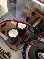
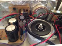
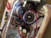
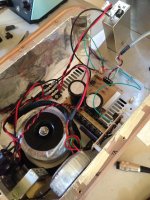
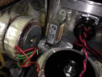
After reading your reply, I wend to my junk-yard and I found new small toroid (18v, 600mA) and built already additional Raw DC line. So, I'm not going to use Folded Raw DC input since I have VU circuit own-independent DC line. Please see attached picture.
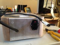
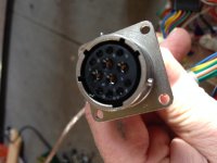
The current issue is the connector from Raw DC to Folded box IN. Till now, I used Lumberg connectors, but I do not have one with 6 lines. I have for 3 and 4 conductors. Do not want to use 2 cables either. I'm going to use more robust one made for military.
Attachments
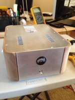
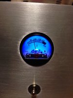
What do you monitor on the PSU's front panel meter? DC voltage or some current?
I monitor AC In. Just as Voltage In indicator.
TT (Welwyn etc.) 15ppm were still very clean and focused but softer than a VAR still not matching its focus. More mellow though. The VAR could be kinda more monitor. TNPW for SMD and RC55Y for through hole were extremely low excess noise just one click above VAR on some resistor noise paper if I remember correctly. Takman Rey and CMF55 are good choices also. PRP has a following too.
TT (Welwyn etc.) 15ppm were still very clean and focused but softer than a VAR still not matching its focus. More mellow though. The VAR could be kinda more monitor. TNPW for SMD and RC55Y for through hole were extremely low excess noise just one click above VAR on some resistor noise paper if I remember correctly. Takman Rey and CMF55 are good choices also.
Have you compared Tx2352 and Tx2575? If so could you share your subjective impression?
Have you compared Tx2352 and Tx2575? If so could you share your subjective impression?
No, I had only used the TX2575 = VAR straight away in a few preamps.
No, I had only used the TX2575 = VAR straight away in a few preamps.
Ok will try the TNPW which i have in hand and maybe will order Susumu RG for a try as well. Have tried Susumu Rg and vishay S102 for passive I/V in my AD1865 dac and the susumu was way better
Is it scaled in VAC or you just judge on some deflection position?
Yes, it is VAC for 300V max.
Attachments
I purchased the Folded Simplistic board. I have 6 2SK170BL that are all around 7.6mA. I see q4 requires 8.2 to 8.5mA but I wanted to know before purchasing some more 2SK170BL if I could use these for q4 and if any changes are needed. If not, I will get some more pieces. I will be using a MM cartridge too.
Thanks
Kerux
Thanks
Kerux
P.S. Some people use less value for load when using Z Foil (Vishay VAR) like 10-20% less than they would on a Tantalum for instance.
Newer use Vihay for load anywhere. For series and feedback a few places they are fine. Too many off them sound is clinical and treble focused.
I am testing my boards. The gain seems too high. What change should I make to fix this.
Left Right
Voltage across R1x 43.7-42.3 = 1.4V 43.7-42.3 = 1.4V
Rail+ 33.3 33.3V
TP1 7.66 7.66V
TP2 4.06 4.06V
Gain
Frequency Input Output (V RMS)
20Hz 5 4.43
100Hz 5 2
1KHz 5 0.42
This is setup for a MM cartridge. Mine is a Nagoaka MP-11 MI. I will be upgrading to an MC later.
R2 = 90.9 Ohms, R13 = 5.6k and R4 is 1.8k
I hope you can read this OK, my extra spaces to make the columns line up got removed.
Thanks
Jim
I purchased the Folded Simplistic board. I have 6 2SK170BL that are all around 7.6mA. I see q4 requires 8.2 to 8.5mA but I wanted to know before purchasing some more 2SK170BL if I could use these for q4 and if any changes are needed. If not, I will get some more pieces. I will be using a MM cartridge too.
Thanks
Kerux
For MM you may lose just a little gain if using the 7.6mA one in Q4. You should only check the voltage between its D=drain and earth and verify that after R11 there will be at least double that in respect to earth. If not, you will have to trim R11 in bit less value to reach that condition. Or you may use R10=7.5K for getting that gain back and then check the DC conditions for that value.
I am testing my boards. The gain seems too high. What change should I make to fix this.
Left Right
Voltage across R1x 43.7-42.3 = 1.4V 43.7-42.3 = 1.4V
Rail+ 33.3 33.3V
TP1 7.66 7.66V
TP2 4.06 4.06V
Gain
Frequency Input Output (V RMS)
20Hz 5 4.43
100Hz 5 2
1KHz 5 0.42
This is setup for a MM cartridge. Mine is a Nagoaka MP-11 MI. I will be upgrading to an MC later.
R2 = 90.9 Ohms, R13 = 5.6k and R4 is 1.8k
I hope you can read this OK, my extra spaces to make the columns line up got removed.
Thanks
Jim
0.42V at 1kHz divided by 5mV makes for 38.5dB. So if there is some experimental error or real deviation it still points to lower gain than 40dB and not to a suspiciously high gain.
For other test frequencies than 1kHz which is 0dB you need factor in the various RIAA curve EQ values in dB.
Are those TP1 and TP2 measurements referred to as each to earth? If yes they are alright.
I think there's typos under Gain, note the values for R2 under 2SK369BL.
I think you need 9.1R, but let the experts confirm.
No, its 91R in MM.
- Home
- Source & Line
- Analogue Source
- Simplistic NJFET RIAA