What I hope to benefit from this is an stable circuit driving reactive loads with possible lower distortion than my concept right now.
The circuit I use right has a bandwidth of 1.2MHz without output inductor and yet stable.
Under all circumstances the solution to make high bandwidth amplifiers is nested feedback.
High bandwidth design will hit back hard, if we are not careful enough. The will pick up any electric emission if we use unshielded signal cables for example.
In CFA's it seems possible while still maintaining unconditional stability.
I don't think CFA plays any role here. For a Cherry compensated amp to remain stable, the requirement is the output stage to have an as low as possible phase shift. This maps, for minimum phase systems, to having an output stage with an as high as possible ULGF.
In an audio amp, it is the output stage that is by large responsible for the most of the phase shift (since it usually defines the lowest frequency open loop pole). A regular (Miller, etc...) compensation in the VAS/TIS or MIC always tries to isolate the output stage pole (and other residual poles) and, by inserting a dominant pole, to push them all as high as possible in frequency when the feedback loop is closed. This can be done by a VFA or CFA, there's nothing specific other than allowing a dominant pole at a convenient (theoretical and practical) frequency of 1-2MHz.
Please always recall that the slew rate of a CFA or VFA has virtually nothing to do with the CFA or VFA ULGF. Slew rate is a large signal property, ULGF is a small signal property, otherwise said, the slew rate and the rise time have virtually nothing in common. So, in a sense, simply saying that CFAs are "fast" can be (and usually is) misleading regarding the frequency properties of the CFA!
Usually, a mosfet output stage is easier to be included in a Cherry compensation loop, since they usually have a higher ULGF compared to a bipolar output stage. I'm suspecting that fast (30MHz) power bipolars were not available when Cherry developed his work. That would explain why his compensation method never went mainstream at his time. Also, as Mr. Self is not a big fan of mosfet output stages, no wonder he was also not happy with the stability results in (slow) bipolar output stages.
What I hope to benefit from this is an stable circuit driving reactive loads with possible lower distortion than my concept right now.
The circuit I use right has a bandwidth of 1.2MHz without output inductor and yet stable.
Under all circumstances the solution to make high bandwidth amplifiers is nested feedback.
High bandwidth design will hit back hard, if we are not careful enough. The will pick up any electric emission if we use unshielded signal cables for example.
We have very similar goals.
")
I had a prototype picking up interference from the signal generator. My signal generator has no shielding. It was a given to me for free. I now know why!
Amazingly, D. Self was unaware of Cherry's papers about output inclusive compensation. Moreover, also the way he was building and testing amps with way too long leads to the output transistors (I've once seen a picture, about 8", aaargh!) made it impossible to get such a compensation scheme stable.
Still holding a grudge against Mr. Self, isn't it?
Also, as Mr. Self is not a big fan of mosfet output stages, no wonder he was also not happy with the stability results in (slow) bipolar output stages.
I also think thats the reason why he is not a fan of it.
This leads-me to a moment of reflexion.Free yourself from convention.
Most of you have so much culture. Every device assembly has a name, and an acronym. Various Cascodes, Constant Current sources, LTPs etc.
Design, todays, seems to be like blocks and stages assembly, VLSI like ?
I remember, when i began my professional life, Jurassic time, we knew so little, and components where so bad (carbon resistances, slow and noisy devices etc.)...
So, everything we did was, in a way, our own invention in a difficult landscape, and amplifiers like a puzzle of a landscape.
On an other side, each change, each try, was subject to careful measurements and listening, so we learned things in a very sensitive way. You know, so far from simulations...
I wonder if this culture, this way to assemble is better , leads to better results, and not an impeachment to innovation. You know, things that happens, sometimes in your reptilian brain, when you try blind, following your feelings.
Passionated, fascinated, i follow the various experiments in this thread... all those simulations, amazing results...And i learned a lot...
But so few of those amplifiers had been really build and listened. So, what did we learn ? Oh yes, the influence of various combinations on distortion numbers or bandwidth... but did this cascode makes the amp more nervous, or, on the contrary, compensate in the right way a tendency to be 'tiring' ? And what components, to balance the best a too marked character...
Real questions, i don't have answers.
Last edited:
He wasn't a big fan of MOSFETs, because he believed in his simulations, based on Jurassic models, that proved MOSFETs were inferior,I also think thats the reason why he is not a fan of it.
Cheers, E.
Esperado, the circuit I have shown has been built, (excluding the input hawksford) the core of it has been playing for more than 2 years, now it's in further exploration. Where the main objective is trying to implement and listen to different compensation schemes.
And different types of power supplies, from linear to switchmode.
And different types of power supplies, from linear to switchmode.
I know, MiiB, one of the reasons i said "so few...'.Esperado, the circuit I have shown has been built,
I'm waiting with great interest your listening impressions, comparing VFA vs CFA, Hawksford or not...
While, i know...it is not easy to share with words, and, here, it seems a pretty dangerous exercise ;-)
You will acquire a great knowledge... regulated or not for both of them, and even regulated switchmode followed by linear cap multiplier...And different types of power supplies, from linear to switchmode.
separated input + VAS stages from OPS...
Curious to see if it correlate my own (provisional) conclusions.
Last edited:
You will acquire a great knowledge... regulated or not for both of them, and even regulated switchmode followed by linear cap multiplier...
separated input + VAS stages from OPS...
Curious to see if it correlate my own (provisional) conclusions.
The idea of use of SMPS is beginning to grow on me. There are certain advantages as long as you can adequately shield / isolate the potential HF noise.
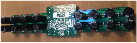
Here's the current state of things. OPS with main distributed supply and an add on smd/PCB with Frontend, Housekeeping, SOA protection, temperature sensing, offset sensing and a Cap/mult for extra + 8V supply.
The frontend has options for different compensations. I dont' know exactly what knowledge I will gain or if it will lead in the right direction.
I have preserved the best sounding of my former trials...
Funny thing this fiddling with small 3 legged critters, I have to understand every thing from a physical perspective, while I see others going at it from a more mathematical point of view. Glad there's such thing as a simulator so I can skip the hardcore math. But as with everything simulation is only a tool to useful for gathering knowledge. Normally we joke about it and say simulation can make a good engineer better, but a bad one really dangerous. Results are only as valid as the information you feed the simulation. Here we even have to question the validity of the selected models.
Attachments
I'm waiting with great interest your listening impressions, comparing VFA vs CFA, Hawksford or not...
Just curious, what makes you trust MiiB listening impressions? Have you had the chance to compare your listening experiences before? Would you also trust, for example, Edmonds' listening impressions? As you see, I'm not asking about mine, since I am an inexperienced nobody.
For the last two weeks have been intensively playing with Miller plus Cherry compensations on a real CFA amp, more here.
Pure Cherry only, the amp stability is on the edge, THD10 around 60 ppm at 100W/4R
Miller only, makes amp stable but elevate THD10 to 90 ppm
Both compensations in their sweet-spot, set by trimmer caps, resulting in 30 ppm. Also 3 MHz sine signal spectrum has lowest THD at this point. Replaced with fixed values caps the end result is now around 40 ppm. So Miller plus Cherry combined works best in my CFA, interestingly all four caps values are very low and very close to each other.
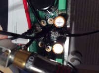
Else what I noticed at live 100W/4R/10kHz test is that moving high current PSU wires around the amp can change THD levels significantly, it can go from 40 ppm to 80 ppm just if they're not positioned correctly.
Pure Cherry only, the amp stability is on the edge, THD10 around 60 ppm at 100W/4R
Miller only, makes amp stable but elevate THD10 to 90 ppm
Both compensations in their sweet-spot, set by trimmer caps, resulting in 30 ppm. Also 3 MHz sine signal spectrum has lowest THD at this point. Replaced with fixed values caps the end result is now around 40 ppm. So Miller plus Cherry combined works best in my CFA, interestingly all four caps values are very low and very close to each other.
Else what I noticed at live 100W/4R/10kHz test is that moving high current PSU wires around the amp can change THD levels significantly, it can go from 40 ppm to 80 ppm just if they're not positioned correctly.
Attachments
Last edited:
VAS being the driver section..??
no, it is not VSSA, measuring done on the First One
Else what I noticed at live 100W/4R/10kHz test is that moving high current PSU wires around the amp can change THD levels significantly, it can go from 40 ppm to 80 ppm just if they're not positioned correctly.
Hi LC,
You are moving the electromagnetic field(s) when cables are moved.
It looks like big distance between the big caps. I believe that placing the big caps and power leads together (incl. PCB terminals) would further reduce distortion.
I was merely trying to get some pointers how my circuit would behave.
You have two stages inside the cherry loop. 3 including the VAS. What I have seen in my sims is that I can get good phase margin with cherry caps alone, but then sims are just sims, and I need to get soldering and measuring to really get to know things for real.
You have two stages inside the cherry loop. 3 including the VAS. What I have seen in my sims is that I can get good phase margin with cherry caps alone, but then sims are just sims, and I need to get soldering and measuring to really get to know things for real.
- Home
- Amplifiers
- Solid State
- CFA Topology Audio Amplifiers