I have no idea how you could do that. The common emitter connection of a LTP is a virtual ground, so that would not work.
Yes, that would work and you have participated in this thread, and did not comment against it. http://www.diyaudio.com/forums/solid-state/221901-little-gem.html
To see if it's a CFA just apply the two tests and two pointers!
...
Single gain stage, whereas VFA is always at least 2 ( the reason why CFA 's are easier to comp BTW)
I have wondered about this for a while.
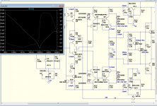
OStripper's amp has essentially the same sections as a classic symmetric VFA.
OPS and VAS/TIS are practically identical and the IPS has similarities to a classic complementary IPS - 2 complementary CCS, each attached to a pair of transistors.
Of course they are LTPs in the VFA, and EF + CE pairs in the "CFA" but still subject to stability analysis in terms of poles, zeros and return ratio.
So why should the CFA be easier to compensate?
It is obviously not because of fewer sections or less transistors.
Just less Loop Gain?
If so then a CFA should be comparable to a low Gain VFA.
Or are the poles and zeros more conveniently placed?
If so where and why?
Can the same benefits be obtained from a VFA with equally low feedback impedances?
Best wishes
David
Last edited:
IMV it's mainly because of the extra loop gain but I would also agree the input stage pole in a VFA cannot be ignored. In a CFA ( because of the lower OLG) the OPS pole sits well below UG - in a VFA it's much closer and can in fact lie above UG. That's why classic VFA (ie MC) is needed - so called dominant pole comp. This pushes the 1st pole down in freq and the HF pole up in freq so it is then well below UG and thus can cause no problems.
It's dominant pole comp that results in constant gain BW response.
Of course, you can apply advanced comp techniques as well to solve the problem like TPC, MIC etc. in VFA.
It's dominant pole comp that results in constant gain BW response.
Of course, you can apply advanced comp techniques as well to solve the problem like TPC, MIC etc. in VFA.
I believe the main reason for that is that in CFA the feedback injection does not add it's own pole, as in VFA where the injection is "polluted" by the capacitance of the backside LTP transistor.
Right but often the feedback network has relatively high Z
in VFA designs , reduce the shunt resistor to about 100R
and the difference between so called CFAs and VFA become
negligible bandwith wise , i posted sims on another thread
showing the results with usual transistors and 5Ghz ft models.
...
So why should the CFA be easier to compensate?
It is obviously not because of fewer sections or less transistors.
Just less Loop Gain?
If so then a CFA should be comparable to a low Gain VFA.
Or are the poles and zeros more conveniently placed?
If so where and why?
Can the same benefits be obtained from a VFA with equally low feedback impedances?
Best wishes
David
I think you said it all. VFA is basically easier to compensate and allows additional complexity till CFA relies on speed. As fewer devices on signal path and return. It can be good thing for audio and some designs proves it. Though there is no reason for VFA not to be fast enough. In this tempting audio art constructor chose what fits him best.
Last edited:
Better 'CFA' type inputs.
Edmond, I'm still not sure what you mean by your initial statement. "We know already that for lowest distortion RE = 0.5/gm = 0.5 VT / Ic or 13mV / Ic at room temperature (and ignoring bulk resistances for a moment)."
At first I thought you were referring to distortion of a single CE amp but your latest stuff suggests this improvement is only for Diamond IPS. Can you confirm this please and explain a little more for us unwashed masses.
I shall have to take your PSR recommendations on trust.
_________________ Poorer PSR?
I think Waly's reason, the CMR of the LTP, rejecting stuff fed via the LTP current tail, has probably the greater effect. Its the reason why PSR is better on one rail for most VFA OPAs .. the other reason is the compensation is usually referred to the other rail.
My $0.02 is that these are only seen cos the Loop Gain of most CFAs are hobbled by the symmetrical topologies adopted.
Anyone have more ideas? Both the above are curable by fairly simple methods.
_________________
Waly posted a circuit in #3149 for which he claims less THD, better PSR (I think) and less IPS dissipation compared to Edmond's in #3135.
Waly, could you explain a little about how this is achieved. I'm having a hard time seeing how this is better than Edmond's 2 examples in #3135.
The input EFs are 'similarly' cascoded as are the CE stages. The main difference seems to be the addition of 2 transistors dedicated to cascoding the input EFs. What do we get for these?
Is it your own invention? Have you tried it in real life? Got some numbers ... preferably 'real life' but SPICE world will do.
__________________
It's good we actually have some practical ideas for better amps .. strewn among the ad nauseum pedantic semantic sh*t.
I'm even more heartened that Guru Cordell has chimed in. Hopefully this means he will devote some space in the new addition of his book to the PROS & CONS of CFA type amps.
If we are really good, he might even burn some solder and report some 'real life' experience.")
For those who haven't been following this thread closely, Edmond posted some stuff about making better amps in #3135I'm not sure which RE you mean, RE1 or RE2?
Anyhow, RE2 is chosen in such a way that gm is neither compressive, nor expansive. IOW, this will give the lowest distortion.
Edmond, I'm still not sure what you mean by your initial statement. "We know already that for lowest distortion RE = 0.5/gm = 0.5 VT / Ic or 13mV / Ic at room temperature (and ignoring bulk resistances for a moment)."
At first I thought you were referring to distortion of a single CE amp but your latest stuff suggests this improvement is only for Diamond IPS. Can you confirm this please and explain a little more for us unwashed masses.
I shall have to take your PSR recommendations on trust.
_________________ Poorer PSR?
This is Edmond's reason for the poorer PSR of CFAs compared with VFAs.This is because of the Early and Cob effect, which, opposed to a LTP-VFA, has not been cancelled. In case of LTP-VFA, both legs of the LTP are subject to these effects and are (largely) cancelled by the action of the current mirror.
I think Waly's reason, the CMR of the LTP, rejecting stuff fed via the LTP current tail, has probably the greater effect. Its the reason why PSR is better on one rail for most VFA OPAs .. the other reason is the compensation is usually referred to the other rail.
My $0.02 is that these are only seen cos the Loop Gain of most CFAs are hobbled by the symmetrical topologies adopted.
Anyone have more ideas? Both the above are curable by fairly simple methods.
_________________
Waly posted a circuit in #3149 for which he claims less THD, better PSR (I think) and less IPS dissipation compared to Edmond's in #3135.
Waly, could you explain a little about how this is achieved. I'm having a hard time seeing how this is better than Edmond's 2 examples in #3135.
The input EFs are 'similarly' cascoded as are the CE stages. The main difference seems to be the addition of 2 transistors dedicated to cascoding the input EFs. What do we get for these?
Is it your own invention? Have you tried it in real life? Got some numbers ... preferably 'real life' but SPICE world will do.
__________________
It's good we actually have some practical ideas for better amps .. strewn among the ad nauseum pedantic semantic sh*t.
I'm even more heartened that Guru Cordell has chimed in. Hopefully this means he will devote some space in the new addition of his book to the PROS & CONS of CFA type amps.
If we are really good, he might even burn some solder and report some 'real life' experience.


As simple as that, yes MiiB. That is what i believe too.as in VFA where the injection is "polluted" by the capacitance of the backside LTP transistor.
At a so sensible point where any resistance quality change in the feedback path can be noticed, the addition of the 'backside transistor' makes a big difference.
I believe we could reach the same transparency with a VFA, used in inverting configuration, where signal+feedback are subtracted passively.
The problem is that, to reach the same FT, it request an input impedance so low that few preamps should be able to drive-it.
Plus the fact that any inductance/capacitance/non linear impedance in the preamp output stage +wires between amp and preamp will bring unexpected evils.
Looking at CFA behaviors, it offers so many advantages that i wonder where Murphy was, when this topology was first imagined.
Let-us continue to reduce the cons. (big thanks to Bonsai,, Dadod, Edmond, Lazy Cat, Manso, ostripper, etc... what a valuable collaborative study)
Last edited:
For those who haven't been following this thread closely, Edmond posted some stuff about making better amps in #3135
Edmond, I'm still not sure what you mean by your initial statement. "We know already that for lowest distortion RE = 0.5/gm = 0.5 VT / Ic or 13mV / Ic at room temperature (and ignoring bulk resistances for a moment)."
At first I thought you were referring to distortion of a single CE amp but your latest stuff suggests this improvement is only for Diamond IPS. Can you confirm this please and explain a little more for us unwashed masses.
I shall have to take your PSR recommendations on trust.
_________________ Poorer PSR?
This is Edmond's reason for the poorer PSR of CFAs compared with VFAs.
I think Waly's reason, the CMR of the LTP, rejecting stuff fed via the LTP current tail, has probably the greater effect. Its the reason why PSR is better on one rail for most VFA OPAs .. the other reason is the compensation is usually referred to the other rail.
My $0.02 is that these are only seen cos the Loop Gain of most CFAs are hobbled by the symmetrical topologies adopted.
Anyone have more ideas? Both the above are curable by fairly simple methods.
_________________
Waly posted a circuit in #3149 for which he claims less THD, better PSR (I think) and less IPS dissipation compared to Edmond's in #3135.
Waly, could you explain a little about how this is achieved. I'm having a hard time seeing how this is better than Edmond's 2 examples in #3135.
The input EFs are 'similarly' cascoded as are the CE stages. The main difference seems to be the addition of 2 transistors dedicated to cascoding the input EFs. What do we get for these?
Is it your own invention? Have you tried it in real life? Got some numbers ... preferably 'real life' but SPICE world will do.
__________________
It's good we actually have some practical ideas for better amps .. strewn among the ad nauseum pedantic semantic sh*t.
I'm even more heartened that Guru Cordell has chimed in. Hopefully this means he will devote some space in the new addition of his book to the PROS & CONS of CFA type amps.
If we are really good, he might even burn some solder and report some 'real life' experience.
Edmond is right. The main contribution too low psrr is the non balanced current when running symmetrical. Due to the early voltage effect, a modulation of vce will mean a modulated hfe. A modulated hfe means that the ibasis is also modulated.
The same problem we have with the current sources.
All This would not be a problem if the ripple was symmetrical, but it isnt.
There is two ways to Solve it . Choose a part with an high early voltage or cascoding. The higher the output impedance of the cascoding the better the psrr are from This stage.
- Sonny


Ostripper, I don't understand your placement of the mirror cascode, why not insert it at the input pair, then you take the cob out of those, that must surely be the main focus
I must agree with Michael. It must be the main focus. The input of the current mirror is more or less static.
Yes, that would work and you have participated in this thread, and did not comment against it. http://www.diyaudio.com/forums/solid-state/221901-little-gem.html
A little attention when posting won't harm. The subject was not the compensation, but a feedback loop closed to the emitter of a LTP, supposed to help with some of the CFA properties
As it is, I don't see any advantage of that compensation method, but then I have not analyzed this in detail.
OS,
BTW, Self warns that thick film resistors are very non linear ( bad voltage coeff) and recommends thin film.
High (average) power film resistors (unless specially designed) may behave very poorly in handling high peak current/power. Even if a 100ohm film resistor is specified at 50W, this doesn't mean it can take peak currents of 0.5-1A without blowing. I would not use such a resistor in the feedback loop (unless the peak current/power is specified in the data sheet). Paralleling resistors works much better.
Waly, could you explain a little about how this is achieved. I'm having a hard time seeing how this is better than Edmond's 2 examples in #3135.
The input EFs are 'similarly' cascoded as are the CE stages. The main difference seems to be the addition of 2 transistors dedicated to cascoding the input EFs. What do we get for these?
Is it your own invention? Have you tried it in real life? Got some numbers ... preferably 'real life' but SPICE world will do.
- Less distortions in the input stage mostly because of the local feedback loop (same as Edmond's).
- Better PSRR because the auxiliary transistors work at more or less constant Vce
- Less dissipation compared to the standard diamond buffer because the input stage transistors don't see the full supply voltage. Also, the auxiliary transistors only see the cascode supply voltage
- The input buffer bias current doesn't go through the gain stage, as a result the gain stage bias is defined only by the diamond buffer current source and two resistor ratio. A little simulation will show that this helps with the recovery when the amplifier is overdriven.
- Not my invention
- Not tried myself in practice, I'm as poor as the next beach bum.
- It's simulated, but not in LTSpice. Visually, if the gain stage and the auxiliary transistors are identical/matched, then they replicate each other, so from an AC perspective it doesn't matter to which emitter you connect the input diamond buffer.
What's happening in this thread is what I would call "design by popularity" rather than based strictly on sound engineering decisions. From this perspective, this little trick adds two transistors, so extra complexity, so obviously it can't sound good/better. So do it yourself in LTSpice and promote it, I hate work and don't have that much spare time to compile results.
Hi Edmond.
Nice to see a perceptive post on this topic, there has been little discussion of optimisation.
But the Oliver condition that 2*RE = 1/Gm was derived for minimum crossover distortion in class B+ circuits.
It is not obvious to me that it is still optimal in this case, what's your rationale?
Compliments of the season and
Best wishes
David
There's also the multi-tanh approach.
Originally Posted by Bonsai
To see if it's a CFA just apply the two tests and two pointers!
...
Single gain stage, whereas VFA is always at least 2 ( the reason why CFA 's are easier to comp BTW)
Very easy to make 1 stage VFA, LTP, folded cascode, shunt Ccomp to ground, and OS.
- Home
- Amplifiers
- Solid State
- CFA Topology Audio Amplifiers