Howdy all.
By way of introduction I have to say that I am probably way out of my depth here in being almost completely ignorant of basic electronics. That said - the reason for my posting is that years back I built what I understand is described as a phase splitter for my Hi Fi music system.
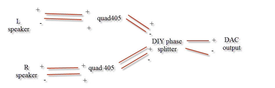
I have a pair of KEF 105 each which is driven by a quad 405 which in turn is fed directly by an Asus Essence STX in a pc which has been tweaked variously to deliver real time sound via ASIO. The output goes to the DIY 'phase splitter' which is supposed to push/pull the left and right channels (each speaker is connected only to +Left and +Right channel output).
The KEF 105 likes this arrangement in general, sounding really unremarkable with a straightforward 100w/ch single channel output from those amps.
The phase splitter I used probably came out of a magazine in the dark ages. It used a 9v battery as simple power supply - later I used a motorcycle 12v battery for year long use. It works fine on 12v.
Thing is that I feel I need to build a new one. I have long lost the schematic and forgotten from where I got it. Sadly what I have was poorly constructed and over the years wires came loose with moving home many times. I reconnected them through nothing more than trial and error. It is a wonder that it still works but saying that I have little faith that it is delivering performance. Without knowledge of basic electronics I cannot look at the configuration (probably has only 8 or so components per channel) and have picture of what is doing what and why.
It strikes me I should build something to replace it from the ground up. There is a pot which one tweaks to get channel A and B in perfect balance. For a simpleton such as I, the fact that it is never possible to get absolute silence (albeit at full volume) via balancing left and right suggests that the thing was never linear even when wired up correctly (ie phases were not perfectly inverted)
I get the idea that the principle of phase splitting is used routinely in amps and I see all sorts of schematics around, I have no idea which of them would suit my stand alone batter powered requirements.
So I would appreciate some suggestions. I might even learn something about what I am constructing if I find the right schematic.
I have a feeling that it may be possible to tweak some of the internals in the quad 405 amps themselves to output without adding another device (my DIY phase spitter) to the signal chain. I see references to 'monobloc' which I am guessing refers to combining separate outputs in stereo amps to drive a single speaker with some extra oomph. Is this what a monobloc is ? Perhaps someone has come across a mod for a Quad 405 Mk1 for this.
many thanks
By way of introduction I have to say that I am probably way out of my depth here in being almost completely ignorant of basic electronics. That said - the reason for my posting is that years back I built what I understand is described as a phase splitter for my Hi Fi music system.
I have a pair of KEF 105 each which is driven by a quad 405 which in turn is fed directly by an Asus Essence STX in a pc which has been tweaked variously to deliver real time sound via ASIO. The output goes to the DIY 'phase splitter' which is supposed to push/pull the left and right channels (each speaker is connected only to +Left and +Right channel output).
The KEF 105 likes this arrangement in general, sounding really unremarkable with a straightforward 100w/ch single channel output from those amps.
The phase splitter I used probably came out of a magazine in the dark ages. It used a 9v battery as simple power supply - later I used a motorcycle 12v battery for year long use. It works fine on 12v.
Thing is that I feel I need to build a new one. I have long lost the schematic and forgotten from where I got it. Sadly what I have was poorly constructed and over the years wires came loose with moving home many times. I reconnected them through nothing more than trial and error. It is a wonder that it still works but saying that I have little faith that it is delivering performance. Without knowledge of basic electronics I cannot look at the configuration (probably has only 8 or so components per channel) and have picture of what is doing what and why.
It strikes me I should build something to replace it from the ground up. There is a pot which one tweaks to get channel A and B in perfect balance. For a simpleton such as I, the fact that it is never possible to get absolute silence (albeit at full volume) via balancing left and right suggests that the thing was never linear even when wired up correctly (ie phases were not perfectly inverted)
I get the idea that the principle of phase splitting is used routinely in amps and I see all sorts of schematics around, I have no idea which of them would suit my stand alone batter powered requirements.
So I would appreciate some suggestions. I might even learn something about what I am constructing if I find the right schematic.
I have a feeling that it may be possible to tweak some of the internals in the quad 405 amps themselves to output without adding another device (my DIY phase spitter) to the signal chain. I see references to 'monobloc' which I am guessing refers to combining separate outputs in stereo amps to drive a single speaker with some extra oomph. Is this what a monobloc is ? Perhaps someone has come across a mod for a Quad 405 Mk1 for this.
many thanks
I don't quite follow the set up here...
You have one Quad 405 ? (not two) so that means one channel per speaker ? When you say "each speaker is connected only to +Left and +Right channel output" then that could be taken as meaning a "bridged" configuration where one channel of an amp is driven out of phase and the speaker connected between the two amps. But you would need two 405's for that for stereo.
Is that what you mean ? Perhaps a quick drawing might help and maybe a photo of this phase splitter (its easy to upload images to the forum)
hopefully this is a better description. I have 2 quad 405 amps - each one which is connected to a single speaker. The wires from each speaker are connected to the two positive poles on the output of each amp. So the negative speaker outputs are ignored.
From the speaker's point of view - the + output for the left channel pushes while the + for the right channel pulls. From my stand alone phase splitter point of view - it sends the same signal albeit 180 degrees out of phase to the Quad 405 input for the left channel and to the right channel respectively.
As I understand it - this changes things impedance wise for the speakers but does deliver 2x power (or 4x in wattage terms). Whatever the technicality - this does suit these speakers which were well known to respond better to their rated 200w/ch than to a mere 100w/ch as delivered by a standard single Quad 405. The difference is quite clear even at low listening volumes.
The contraption I build does deliver a large improvement in sound quality but it makes sense on a number of levels that this primitive and now probably miswired thing should be replaced with something better
hope that helps -thanks for replying
OK... hmmm
So it is just a simple phase splitter you have. For several reasons I'm not convinced that the Quads are a good candidate for "bridging" as its called... however")
Well, building a simple phase splitter with opamps is dead easy although 12 volts is a little on the low side... but that applies to what you have now whether its discrete (separate transistors) or using opamps. You could build a phase splitter into each Quad and run it from the Quads internal supply.
I'll have to leave it for tonight but I can come up with a simple and good phase splitter using opamps. Its just one 8 legged opamp and a few resistors.
So it is just a simple phase splitter you have. For several reasons I'm not convinced that the Quads are a good candidate for "bridging" as its called... however
Well, building a simple phase splitter with opamps is dead easy although 12 volts is a little on the low side... but that applies to what you have now whether its discrete (separate transistors) or using opamps. You could build a phase splitter into each Quad and run it from the Quads internal supply.
I'll have to leave it for tonight but I can come up with a simple and good phase splitter using opamps. Its just one 8 legged opamp and a few resistors.
Appreciate the help and look forward to any suggestions I would be very keen to try.
The system (sans the DAC which is newer) sat in storage for more than a decade during which I had zero exposure to any kind of quality sounds. It all sounds pretty amazing to my ear presently, but surely it could sound yet better with a bit of work.
The system (sans the DAC which is newer) sat in storage for more than a decade during which I had zero exposure to any kind of quality sounds. It all sounds pretty amazing to my ear presently, but surely it could sound yet better with a bit of work.
If you intend to build a high quality phase splitting circuit then it may not be so simple. I have built a phase splitter before of my own design but it is not simple. However, there is a much simpler solution. I have not used them before but have heard they work quite well. THAT1646. I have used the matched arrays from THAT corp. They work swell. In fact I used them to make my discrete phase splitter circuit.
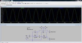
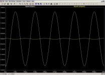
Here is an opamp based splitter. You could use something like the LM4562 or OPA2314 which are dual opamps and power these from the existing opamp already in use in the Quad. So its one dual opamp and 6 resistors. The picture shows the two outputs and the exact 180 degree shift. Using opamps and the split is perfect.
Attachments
thanks for that, very grateful and it promises to be rather less messy than what I presently have - there will probably be a pause for a while to get components and figure out where it all goes.
Meantime on the trivial level - as memory serves me, the term 'bridging' was once bandied about as distinct from what I have been using - namely the configuration wherein one gangs up both L&R+ outputs from the amp to one wire to the speaker and the other wire from the speaker goes back to the negative on the amp. There, one still needed to match the output of the left and right channels so that one did not feedback into the other.
Am I dreaming that one up? I had the impression that would provide create a signal with different impedance characteristics, presumably more or less suited to different speakers.
I am interested in your statement that the Quad 405 is not especially suited to the bridging configuration.
Easy one first and why I don't think the Quad is ideal...
Lets say you have the Quad wired conventionally and providing an output voltage of +30 volts (I know music is AC but lets work DC as its easier to follow and the numbers are the same). And lets say you have an 8 ohm speaker (but is it... I'll explain later ?). So 30 volts across 8 ohms dissipates 112.5 watts. Its just 30 squared divided by 8. The current is 3.75 amps.
Now we bridge the amps and invert the signal to the other channel connecting the load across the two positive outouts now. So we have +30 on one amp and -30 on the other. The load sees 60 volts. That gives a power of 450 watts and a current flow of 7.5 amps.
Now the big problem is that the Quad isn't designed to handle that kind of current output. It will be pushing the output stage beyond its safe limits if driven hard enough. The problem can be worse because that 8 ohm speaker might actually be nothing like an 8 ohm resistor but instead be "reactive" where the current and voltage end up out of phase with each other and also where the "impedance" varies considerably. My own B&W703's are described as 8 ohm and yet the "impedance" (the AC equivalent of resistance) falls as low as 3 ohm. Calculate all the above for 3 ohm and things start getting tough. The amp just isn't designed to handle that current.
Going back to the circuit. Yes, that's all you need to make a perfect splitter. Refinements might include AC coupling the inputs. You would also be advised to add a decoupling cap across the opamps power supply pins close to the opamp. Something like a 10uf63v cap would be perfect.
I intend to construct the opamp circuit suggestd by Mooly but was just thinking that whereas the splitter may be perfect, the two channel modules in the amp are unlikely to be perfectly matched.
So I am guessing that I would need to include some kind of pot to try to balance the two channels. It seems to me that before including the opamp circuit that one should regulate the L+R inputs such that when the speaker is connected to the left and right + channels that no sound can be heard. In other words the left and right channels push and pull with equal strength.
I suppose it is wishful thinking to expect the differences to be linear but without fancy equipment there are always going to be differences and mismatches between the two channels which may not be fixed with a simple pot. Are regular pots linear?
...and anyway, is it likely that the left and right quad 405 channel modules are going to remain stable over time?
Is there any smart DIY solution I could try for dealing with this? Without careful analysis it is hard to know what level of imperfections will be audible at the end of the day. In theory turning up the volume with both + channels connected to the speaker and hearing nothing (or near nothing) is 'the' practical test.
Before shopping for components I guess my query boils down to - what kind of pot is suitable to regulate one of the inputs to the power amp - or is it worth using some more exotic method to balance the two amp modules?
thanks again for the comment - it is only common sense that this will present some disadvantages although 2 things
1/ that I have used this this configuration (more or less perfectly implemented by my 'kit' splitter for years and even recently did AB listening tests on these particular speakers with single channel use (as designed) versus the phase split version and the results are night and day.
2/ I wont be driving this anywhere close to its limits since I have neighbors but I can hear that the amps are not happy when driven very hard. I am more interested in the quality of the sound in the middle usage range.
I will report back when I have built the splitter you suggest and hope to report an improvement in the sound.
It could all be a lot closer matched than you think. The beauty of negative feedback (which all these amplifiers use) is that the gain relates to the feedback factor and that is as close as the tolerance of the parts.
That said, if you want to be able to trim the gain and get it absolutely identical then that's easily done. You could replace R4 in my diagram above with a 9.1K resistor that has a 2.2k multiturn trimmer in series with it. That would swing the gain of that output a little higher and a little lower than -1
To equalise the gains you could play a test tone of say 400hz or so and set the speaker output voltages to be equal on a DVM on AC volts (as long as the meter has high enough resolution. Set the volume for say 1.500 volts on the non inverted channel and adjust the pot to equalise the other.
Its probably easier doing the gain adjustment on the splitter rather than altering the Quad which has two feedback systems, one for the opamp front end and one for the main power section.
And lastly... I suspect you don't actually need worry and that it will be very very accurate without any worries of tweaking.
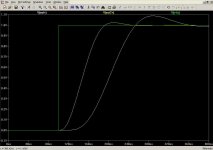
Here is an opamp based splitter. You could use something like the LM4562 or OPA2314 which are dual opamps and power these from the existing opamp already in use in the Quad. So its one dual opamp and 6 resistors. The picture shows the two outputs and the exact 180 degree shift. Using opamps and the split is perfect.
Mooly, the phase splitter circuit you posted has the serious defect that the two signals are not exactly synchronous.
The percentage error in time between the two signals is greater when the signal itself rising in frequency.
But just at the 1 KHz of your example you may notice the delay of one signal with respect to the other.
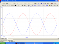
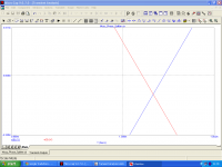
I have done simulations with microcap of your circuit and I attach the waveforms of the two output signals in phase opposition.
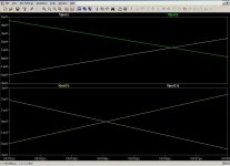
To highlight what I'm saying here is need a greater resolution for which in the first image I posted the transient analisys for two whole periods and in the second image I made a zoom in the point of zero crossing after one period.
It's evident how the output signal from node 8 (in blue) is delayed with respect to the output signal on node 9 (in red). Can you immagine what happen with an input signal of 10 or 100 KHz?
Francesco
Attachments
Hi Francesco and thanks for the observations
What OpAmp did you use for your simulation ?
Yes, its true that passing a signal through any amplifier of finite bandwidth delays the signal (and here we have one opamp for one phase and two for the other).
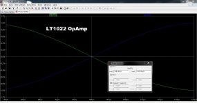
The opamp I used to illustrate the circuit was little more than a 741. Use a higher speed device and the effect diminishes rapidly such as here where I'm using a more representative LT1022 (8.5gbw and 26v/us). I would recommend something like an LM4562 for a real build.
Is such an effect audible anyway ? The difference at hf with a good (fast) opamp is I would imagine is less than the effect of moving a speaker a few millimetres in position.
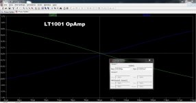
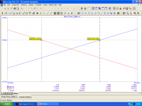
Here is the LT1022 now at 10kHz vs the slower LT1001
Edit If gav is wondering why I'm using LTxxxx devices in the simulation and recommending others to use for real its just because the LT devices are included standard parts with the simulation package.
What OpAmp did you use for your simulation ?
Yes, its true that passing a signal through any amplifier of finite bandwidth delays the signal (and here we have one opamp for one phase and two for the other).
The opamp I used to illustrate the circuit was little more than a 741. Use a higher speed device and the effect diminishes rapidly such as here where I'm using a more representative LT1022 (8.5gbw and 26v/us). I would recommend something like an LM4562 for a real build.
Is such an effect audible anyway ? The difference at hf with a good (fast) opamp is I would imagine is less than the effect of moving a speaker a few millimetres in position.
Here is the LT1022 now at 10kHz vs the slower LT1001
Edit If gav is wondering why I'm using LTxxxx devices in the simulation and recommending others to use for real its just because the LT devices are included standard parts with the simulation package.
Attachments
Hi Francesco and thanks for the observations
What OpAmp did you use for your simulation ?
I have used LT1001 as you.
With LT1022 things are much better, although still remains a small delay of about 35 nsec between the two signals as per attached picture.
To achieve a good phase splitter is very difficult and in fact this stage is generally the most critical, but by it largely depends the quality of an amplifier .
If the two signals are delayed relative to one another, we will lose accuracy in the output signal from the amplifier , then a loss of definition, of detail, of small environmental information and poor focus.
I have not checked instrumentally , but I hypothesize that this delay can also create a distortion similar to the cross-over distortion in class AB ouput stage, with the aggravating circumstance that it is not curable even by a relatively high bias .
On my site I have a page dedicated to the various types of existing phase splitters, summarizing the informations collected on various good websites. A good source of information for those who wish to explore these issues.
New Phase Splitter/Inverter AMPLIMOS one stage amplifiers
In the end, you will also find schemes related to a class of phase splitters designed by me
 with a description of their functioning.
 Your comments are welcome.
greetings
Francesco
Attachments
Thanks for the link, I'll try and find time later. A lot going on at the moment with all the "listening tests threads"
(Do you remember the early days of CD and players using shared DAC's. That gave a significant phase delay of one channel vs the other yet it was never a "major" issue. Around 11us I think which is magnitudes more than any errors here)
(Do you remember the early days of CD and players using shared DAC's. That gave a significant phase delay of one channel vs the other yet it was never a "major" issue. Around 11us I think which is magnitudes more than any errors here)
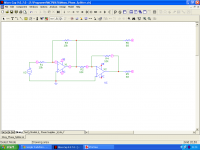
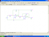
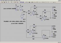
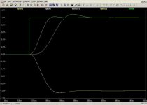
If you use one op-amp to buffer your input signal and one to invert you can eliminate the delay difference between the inverting and non-inverting outputs. (Vout=original, Vout2=Improved)
Schematic, Pulse response, Output difference at 10Khz, Easier to see pulse.
Schematic, Pulse response, Output difference at 10Khz, Easier to see pulse.
Attachments
Last edited:
- Status
- This old topic is closed. If you want to reopen this topic, contact a moderator using the "Report Post" button.
- Home
- Amplifiers
- Solid State
- newbee phase splitter question