You see hochopeper, I did not do any gentle poking into multi channel direction, hehehe! 

Ian,
Thank you for finding time for me. I knew that GB must be killing you. I understand what are you saying regarding Si570. It was just an idea I had that I needed to check. Now, you are completely correct, your multichannel FIFO is exactly what I will need, and not just me but tens of others. As for the holding my projects, let me assure you, what you mentioned in that sentence, is worth holding for.
The project / idea I am trying to achieve seems to be the stumbling block for many. My multichannel USB I2S converter is capable of working in master or slave mode. Behind that converter I will have two independedant DAC boards. Ideally USB board should be Slave and DACs masters. If that is not possible or hard to do, than it could work as Master, but DACs will be Slave. That is scenario that anyone wishing to do digital crossover has. The only other possible option is DSP in between, but there are only few options there, and complexity becomes really challenging.
You see idea of two FIFOs did come to my mind but I was thinking that would not be allowed for some difference in timing between the boards? But even if possible, how I would distribute all those signals between USB board, two Fifos and two DACs from one clock board?
I will tell you... I am not going to take any time away from you. I am just starting with my project and it will be some time before I come to the position to have it all done. The solution is multichannel FIFO and if you are where you are, you will be done before I am. So I will wait. Otherwise I just create noise that takes away your precious time. And FIFO multichannel, will be the ultimate and the cleanest possible solution.
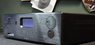
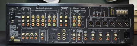
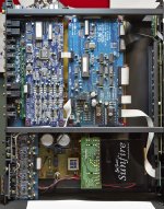
Now, let me make you smile little bit, since you are in the mood to make three out of one... Here is my case for the next project I am talking about. I spent big bucks on it... $79.00, hehehe. It was broken, but there are so manny goodies already inside. The best one is trafo with 18 secondaries...
Ian,
Thank you for finding time for me. I knew that GB must be killing you. I understand what are you saying regarding Si570. It was just an idea I had that I needed to check. Now, you are completely correct, your multichannel FIFO is exactly what I will need, and not just me but tens of others. As for the holding my projects, let me assure you, what you mentioned in that sentence, is worth holding for.
The project / idea I am trying to achieve seems to be the stumbling block for many. My multichannel USB I2S converter is capable of working in master or slave mode. Behind that converter I will have two independedant DAC boards. Ideally USB board should be Slave and DACs masters. If that is not possible or hard to do, than it could work as Master, but DACs will be Slave. That is scenario that anyone wishing to do digital crossover has. The only other possible option is DSP in between, but there are only few options there, and complexity becomes really challenging.
You see idea of two FIFOs did come to my mind but I was thinking that would not be allowed for some difference in timing between the boards? But even if possible, how I would distribute all those signals between USB board, two Fifos and two DACs from one clock board?
I will tell you... I am not going to take any time away from you. I am just starting with my project and it will be some time before I come to the position to have it all done. The solution is multichannel FIFO and if you are where you are, you will be done before I am. So I will wait. Otherwise I just create noise that takes away your precious time. And FIFO multichannel, will be the ultimate and the cleanest possible solution.
Now, let me make you smile little bit, since you are in the mood to make three out of one... Here is my case for the next project I am talking about. I spent big bucks on it... $79.00, hehehe. It was broken, but there are so manny goodies already inside. The best one is trafo with 18 secondaries...
Attachments
You see hochopeper, I did not do any gentle poking into multi channel direction, hehehe!

Some time, I need switch gear for a while. I was trying to fix iMac at board/BGA level last month. Now we have three iMac27s, form 2009 to 2011 models, one for myself, one for my son and other one for my mother in law
Ian, I can't give any technical advice, but based on extensive life experience, I would fix the mother in law one first...
Ian, I can't give any technical advice, but based on extensive life experience, I would fix the mother in law one first...
Thank you for sharing your experience, did exactly that way
Ian
i guess the two concerns for using the tps7a4700 regulator in my application would be:
1.) inductance of the lead wire from the mc7809 to the vin of the tps7a4700. probably this would be ~60nH for a 6cm or so length of 22awg wire.
2.) the 60uF of mlcc output capacitors.
i ordered a few parts tonight:
for the nr capacitor:
epcos mkt 1uF/63v 5% pet
epcos mkt .47uF/63v 5% pet
for the input capacitor:
panasonic fm 330uF/25v
nichicon kz 100uF/50v
and possibly to solder onto the output (probably onto the tail leads of the 2.54mm 3 pin header):
nichicon ka 47uF/50v
will the inductance be an issue, given that it is *before* the input capacitors on the regulator? the datasheet mentions the potential for resonance with even a couple nH of inductance, but perhaps this would only be if it was between the input capacitor(s) and the input to the regulator? would adding additional capacitance (ie. the 330uF fm, or 100uF kz), alongside the 200uF tantalums serve to dampen this?
and, will the use of only mlcc at the output lead to a harsh sound in this analog application? would adding that 47uF ka alongside the mlcc smooth things out a bit? the datasheet is very specific about the use of ceramics for this regulator, but most of what i've read favors electrolytics+film for bulk capacitance in analog power supplies.
thanks for any input on which configuration would be best. i'm hoping to upgrade, not downgrade, this dac but i'm definitely a novice.
-matt
1.) inductance of the lead wire from the mc7809 to the vin of the tps7a4700. probably this would be ~60nH for a 6cm or so length of 22awg wire.
2.) the 60uF of mlcc output capacitors.
i ordered a few parts tonight:
for the nr capacitor:
epcos mkt 1uF/63v 5% pet
epcos mkt .47uF/63v 5% pet
for the input capacitor:
panasonic fm 330uF/25v
nichicon kz 100uF/50v
and possibly to solder onto the output (probably onto the tail leads of the 2.54mm 3 pin header):
nichicon ka 47uF/50v
will the inductance be an issue, given that it is *before* the input capacitors on the regulator? the datasheet mentions the potential for resonance with even a couple nH of inductance, but perhaps this would only be if it was between the input capacitor(s) and the input to the regulator? would adding additional capacitance (ie. the 330uF fm, or 100uF kz), alongside the 200uF tantalums serve to dampen this?
and, will the use of only mlcc at the output lead to a harsh sound in this analog application? would adding that 47uF ka alongside the mlcc smooth things out a bit? the datasheet is very specific about the use of ceramics for this regulator, but most of what i've read favors electrolytics+film for bulk capacitance in analog power supplies.
thanks for any input on which configuration would be best. i'm hoping to upgrade, not downgrade, this dac
but i'm definitely a novice.-matt
Ian, I can't give any technical advice, but based on extensive life experience, I would fix the mother in law one first...
See I take the opposite strategy, though it's not without risk, if I don't repair her stuff then I don't get 101 technical support questions about her problems using safari or itunes or something else mind-numbingly boring
Hi Ian
Can Silab Si590 works on Dual XO Board X1 X2 as 90.3168 and 98.304MHZ?
Thanks
Hi curryking,
You can use Si590 with CMOS output verison. The only thing is the 100mA power consumption. LifePO4 Battery direct power is highly recommended for this application.
Or, you can use Si532 or Si533 0.3ps dual frequency XO, but you will need a special adapter.
Ian
You see hochopeper, I did not do any gentle poking into multi channel direction, hehehe!
Ian,
Thank you for finding time for me. I knew that GB must be killing you. I understand what are you saying regarding Si570. It was just an idea I had that I needed to check. Now, you are completely correct, your multichannel FIFO is exactly what I will need, and not just me but tens of others. As for the holding my projects, let me assure you, what you mentioned in that sentence, is worth holding for.
The project / idea I am trying to achieve seems to be the stumbling block for many. My multichannel USB I2S converter is capable of working in master or slave mode. Behind that converter I will have two independedant DAC boards. Ideally USB board should be Slave and DACs masters. If that is not possible or hard to do, than it could work as Master, but DACs will be Slave. That is scenario that anyone wishing to do digital crossover has. The only other possible option is DSP in between, but there are only few options there, and complexity becomes really challenging.
You see idea of two FIFOs did come to my mind but I was thinking that would not be allowed for some difference in timing between the boards? But even if possible, how I would distribute all those signals between USB board, two Fifos and two DACs from one clock board?
I will tell you... I am not going to take any time away from you. I am just starting with my project and it will be some time before I come to the position to have it all done. The solution is multichannel FIFO and if you are where you are, you will be done before I am. So I will wait. Otherwise I just create noise that takes away your precious time. And FIFO multichannel, will be the ultimate and the cleanest possible solution.
Now, let me make you smile little bit, since you are in the mood to make three out of one... Here is my case for the next project I am talking about. I spent big bucks on it... $79.00, hehehe. It was broken, but there are so manny goodies already inside. The best one is trafo with 18 secondaries...
Hi AR2,
It seems we can start a project competition to see who can finish first
.Yes, if use a multi-channel FIFO, your project can become very flexible . The digital crossover and other digital front end can work at both master mode and slave mode. The first mode might be easier for integrating with anything else, but the second mode can use FIFO with smaller depth to reduce the FIFO delay. But we need digital front end providing signals for switching Fs, if clock signal was fed from FIFO clock board.
Multi-channel FIFO its self is not a big deal, actually the kernel DDR memory and FIFO verilog code has already been done. But to integrate with digital audio systems with perfect, I need to take many things into account, it's gonna be a big picture. The whole architecture will be totally different from current stereo FIFO. I may open a new thread to develop this multi-channel I2S/DSD FIFO project.
Your sunfire processor looks great, it listed $400 on eBay, how could you get it for only $79
 . The case has very good quality as same as Krell, do you really just want to take the transformer?
Regards,
Ian
Last edited:
Hi AR2,
It seems we can start a project competition to see who can finish first
Yes, if use a multi-channel FIFO, your project can become very flexible . The digital crossover and other digital front end can work at both master mode and slave mode. The first mode might be easier for integrating with anything else, but the second mode can use FIFO with smaller depth to reduce the FIFO delay. But we need digital front end providing signals for switching Fs, if clock signal was fed from FIFO clock board.
Multi-channel FIFO its self is not a big deal, actually the kernel DDR memory and FIFO verilog code has already been done. But to integrate with digital audio systems with perfect, I need to take many things into account, it's gonna be a big picture. The whole architecture will be totally different from current stereo FIFO. I may open a new thread to develop this multi-channel I2S/DSD FIFO project.
Your sunfire processor looks great, it listed $400 on eBay, how could you get it for only $79
Regards,
Ian
Maestro,
I know better, than to race with you, hehe. I will only accept it if that gives you inspiration and boost in speed
You are correct Sunfire typically goes for that price on eBay, but mine was not working completely, it was listed as broken, so they listed it for I believe $ 35. There were just two other people interested and with bidding I ended up at $ 79. I certainly did not buy it for the trafo only. I primarily took it for the case, but since that unit is a processor, than it uses all the same voltages I will need thru out. So trafo is added benefit and it is an octopus with so many different windings at monstrous 260VA for this type of applications. Majority of voltages I could use. Ideal to give all separate winding / feeds to pre-regulators for analog, digital parts off and L and Right DAC boards, clock IVs, FIFO, isolator circuits...
Case has all I wanted: It is as big as big receiver, so it gives a lots of room for all different boards and power supplies. Than front panel is feast on its own. Big window to accommodate any VFD display I will be replacing, than tons of momentary switches, two!!! rotary encoders with attached buttons that I could always replace if these do not work with Arduino. So all that saves me a tons of machining work, and time is what I am short with. Case looks like from the box with no scratches, so I came very good with this. It is already gutted out and is waiting for all my boards to be fitted.
For someone who is good with microprocessors and programming, there is all that there that could be hacked and reprogrammed to control all kinds of switching and integrated in project. Certainly not me, I will be just hacking front panel circuit board and linking switches, display and rotary encoders to Arduino.
As for multichannel FIFO a shorter delay sounds very good. If I could influence in any way, I would suggest to integrate input board, FIFO and isolators on one board, and maybe (just maybe) have separate clock board for possibility of experimenting with various clocks. That way might be more compact and easier to integrate or to pack.
It seems like you are onto something special. I know all the eyes and ears around the globe are wide open, so you might stock up on packaging materials. I certainly wish you all the success. Now, let me go back to soldering, time is ticking, race is on...
Best
AR2
Shorter delay must be a requirement. I was not successful in lip-syncing a Oppo-105 as a drive to an Ian FiFo based DAC. Not even on the Oppos largest time adjustment which I think is 200ms.
There isn't a way to take a SQ penalty to achieve less delay in the current product - righth?
There isn't a way to take a SQ penalty to achieve less delay in the current product - righth?
Shorter delay must be a requirement. I was not successful in lip-syncing a Oppo-105 as a drive to an Ian FiFo based DAC. Not even on the Oppos largest time adjustment which I think is 200ms.
There isn't a way to take a SQ penalty to achieve less delay in the current product - righth?
I think that FIFO implementation is not suitable for video. My understanding is that simply without the delay FIFO would not be able to function. I do not know if any software has that amount of delay available for video synchronization. Maybe some kind of I2S bypass circuitry could be made where for video FIFO is bypassed and for music is switched back? The difficulty with that is that it adds complexity to a fragile I2S signal.
Long time ago, I decided that it makes life much easier if music and video set ups are separated, so in my house I have a separate system dedicated for movies or TV and do not bother at all playing music there. The main benefit is - wife is capable of operating it on her own, hehe. It is all synchronized through HDMI, no IR mismatches when turned on, only one remote that really works. Just that benefit keeps me sane.
Maestro,
As for multichannel FIFO a shorter delay sounds very good. If I could influence in any way, I would suggest to integrate input board, FIFO and isolators on one board, and maybe (just maybe) have separate clock board for possibility of experimenting with various clocks. That way might be more compact and easier to integrate or to pack.
It seems like you are onto something special. I know all the eyes and ears around the globe are wide open, so you might stock up on packaging materials. I certainly wish you all the success. Now, let me go back to soldering, time is ticking, race is on...
Best
AR2
Hi AR2
Same ideas with you.
1. There will be three input ports on the FIFO board. At least one multi-channel I2S/DSD port and one stereo I2S/DSD port. What do you think the third one?
2. For sure, isolator will be integrated. But I'm still not decide to integrate it on FIFO or on clock board. The advantage of placing isolator on the clock board is obvious - making all ground and signals shorter and closing to DAC, while isolating to anything else.
3. A control port will be there to connect to an external controller or pannel/display. Protocol will open to third party controllers.
Please let me know your point.
Have a nice week.
Ian
1. There will be three input ports on the FIFO board. At least one multi-channel I2S/DSD port and one stereo I2S/DSD port. What do you think the third one?
I would say its never too many I2S inputs
. But it might be more practical to have some kind of switcher instead of too many inputs. In my mind, that multi channel I2S input could serve as stereo input as well, right? Than we have right there:A. Two Stereo I2S or One Multichannel and one Stereo
B. S/PDIF, AES/EBU, Toslink I would say optional with your existing input board?
If I am just selfishly thinking, for my own situation, this would be the ideal scenario at the input: Multichannel USB to I2S, S/PDIF and on a second I2S input I would love to se ADC based on this:
ESS Products - ADC
The reason having a ADC is for anyone having digital crossover, has to go through ADC if desired to play analog source.
So two I2S and S/PDIF. Plenty would be three I2S or switcher instead.
2. For sure, isolator will be integrated. But I'm still not decide to integrate it on FIFO or on clock board. The advantage of placing isolator on the clock board is obvious - making all ground and signals shorter and closing to DAC, while isolating to anything else.
I am sure I am not the right one to give advice on this. This should be your call.
3. A control port will be there to connect to an external controller or pannel/display. Protocol will open to third party controllers.
That is really great. Lets not forget option to send the right signal to Arduino regarding sample rate reading.
My best
Vladimir
Sorry my stupid question, but what do i have to configure on the Dual XO Clock board after replacing the clocks with crystek 45 and 49 mhz? What is the correct setting of the jumpers TP4-5,5-6,6-7,7-8? I´ve pressed a few times the onboard switch but i´ve forgot the default setting...
I´m using waveio with latest firmware, fifo and isolator board. I´m feeding the waveio isolator with 5v from the fifo board
thx in advance
I´m using waveio with latest firmware, fifo and isolator board. I´m feeding the waveio isolator with 5v from the fifo board
thx in advance
I see most guys are mounting all the boards on plexiglass or something like that.
I have never built such a complex digital setup, so I am wondering why this seems to be the best practice.
I guess it is done to avoid ground loops, but don't I get ground loops anyways, if I feed all the boards with PSUs that share the same ground? (Because boards will have ground connections via the signal cables and PSU ground.)
- Home
- Source & Line
- Digital Line Level
- Asynchronous I2S FIFO project, an ultimate weapon to fight the jitter